Product Description
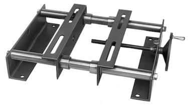
SMA Common Base:
Characleristics: galvanization finish, with split platesslidling, it’s convenient for bolts fixing of motors.
Application: fixing and adjustment of all series motors.
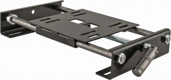
MP Motor Base:
Characteristics: gavanization fnish WTH MONOPLATE SLIDNG,bending and pressing
Applcatiorne the HangZhoug and adjustment of large power motors.
MB Type Motor Pedestal:
Characteristics: welded with high quality steel, powder coating finish, with matched fixing screw ofmotors, it is much convenient for fixing and adjustment.
Application: Application: suitable for the fixing and adjustment of large,medium and small power motors.
DHA Motor Rail:
it is with unique design, beautiful appearance, steady fixing and powerful weight bearing. It can be widely uesd in the fixing and adjustment of different kinds of motors.
characteristics:
Made of high quality steel with pressing and processing. It is with matched fixing screw of motor, much convenient for adjustment.
Application: the fixing and adjustment of different kinds of motors.
Main Products:
Timing belt pulleys, timing bars, timing belt clamping plates.
Shaft locking devices (assemblies) and shrink discs: could be alternative for Ringfeder, Sati, Chiaravalli, BEA, Tollok, etc.
V belt pulleys and taper lock bush.
Sprockets, idler, and plate wheels.
Gears and racks: spur gear, helical gear, bevel gear, pinion gear, worm gear, gear rack.
Shaft couplings: miniature coupling, curved tooth coupling, chain coupling, HRC coupling, normex coupling, FCL coupling, GE coupling, rigid and flexible coupling, jaw coupling, disc coupling, multi-beam coupling, universal joint, torque limiter, shaft collars.
Forging, Casting, Stamping Parts.
Other customized power transmission products and Machining Parts (OEM).
/* January 22, 2571 19:08:37 */!function(){function s(e,r){var a,o={};try{e&&e.split(“,”).forEach(function(e,t){e&&(a=e.match(/(.*?):(.*)$/))&&1
| Standard or Nonstandard: | Standard |
|---|---|
| Feature: | Flame-Retardant, Anti-Static, Oil-Resistant, Cold-Resistant, Corrosion-Resistant, Skid-Resistance, Wear-Resistant, Acid-Resistant |
| Application: | Motor |
| Surface Treatment: | Zinc Plating |
| Material: | Carbon Steel |
| Standard: | European Standard |
| Samples: |
US$ 10/Piece
1 Piece(Min.Order) | |
|---|
| Customization: |
Available
|
|
|---|
Can motor slide rails be retrofitted to existing motor installations, or are they primarily for new setups?
Motor slide rails can be retrofitted to existing motor installations, providing flexibility and adaptability to various setups. Here’s a detailed explanation:
Motor slide rails are versatile components that can be used in both new motor setups and retrofitting applications. They are designed to facilitate linear motion and provide a controlled mechanism for moving motors along a defined path. The retrofitting capability of motor slide rails allows for the upgrade or modification of existing motor installations without the need for significant structural changes or replacements.
When considering the retrofitting of motor slide rails to an existing motor installation, several factors need to be taken into account:
1. Compatibility:
It is important to ensure that the motor slide rails are compatible with the existing motor and the surrounding components. This includes considering the dimensions, weight, and mounting requirements of the motor. The slide rails should be able to support the weight of the motor and any additional loads. Additionally, the slide rails should align with the mounting brackets or other attachment points of the motor.
2. Space Constraints:
The available space and layout of the existing motor installation should be considered when retrofitting motor slide rails. The slide rails should fit within the available space without interfering with other equipment or components. It may be necessary to make adjustments or modifications to accommodate the slide rails, such as rearranging surrounding equipment or repositioning existing components.
3. Installation Considerations:
The retrofitting process of motor slide rails requires careful planning and installation. It is important to follow the manufacturer’s instructions and guidelines for proper installation. This may involve disassembling parts of the existing motor installation, attaching the slide rails securely, and reassembling the components. Attention should be given to proper alignment, attachment points, and ensuring smooth movement along the slide rails.
4. Performance and Safety:
Retrofitting motor slide rails to an existing motor installation can offer improved performance and safety. The controlled linear motion provided by the slide rails can enhance the stability, positioning accuracy, and ease of maintenance of the motor. It is essential to assess the potential benefits and any safety considerations associated with retrofitting slide rails to ensure they align with the goals and requirements of the specific application.
In summary, motor slide rails can be retrofitted to existing motor installations, offering flexibility and adaptability to various setups. The retrofitting process requires considering compatibility, space constraints, installation considerations, and the potential performance and safety benefits. By carefully evaluating these factors and following proper installation procedures, motor slide rails can be successfully incorporated into existing motor setups, allowing for improved functionality and ease of maintenance.
Can motor slide rails accommodate various motor mounts and couplings?
Yes, motor slide rails are designed to accommodate various motor mounts and couplings. Here’s a detailed explanation:
Motor slide rails are versatile components that can be integrated into motor installations with different types of motor mounts and couplings. They are designed to provide a universal platform for mounting motors, allowing for flexibility and compatibility with a wide range of motor configurations.
1. Motor Mounting Options:
Motor slide rails are typically designed with multiple mounting options to accommodate different motor mounts. These mounting options can include slots, holes, or threaded inserts that allow for the attachment of various motor mounting brackets or plates. The flexibility in motor mounting options enables the use of different motor mount designs, such as foot mounts, flange mounts, or face mounts. Motor slide rails provide a secure and adjustable interface for connecting the motor mounts to the rail system.
2. Coupling Compatibility:
Motor slide rails can also accommodate various types of motor couplings. Motor couplings are used to connect the motor shaft to the driven equipment, such as a gearbox or a load-bearing mechanism. Different types of couplings, such as flexible couplings, rigid couplings, or torsionally flexible couplings, have specific dimensional requirements and attachment methods. Motor slide rails are designed to provide sufficient space and clearance for the installation of different types of motor couplings. They allow for easy integration of the coupling components, ensuring proper alignment and connection between the motor and the driven equipment.
3. Adjustable Mounting Positions:
One of the key advantages of motor slide rails is their adjustable mounting positions. They provide a range of positions along the rail where the motor can be secured. This adjustability allows for fine-tuning the motor position and aligning it with the driven equipment or other components in the system. The ability to adjust the motor position using the slide rails accommodates variations in motor mount dimensions and facilitates precise alignment of the motor and coupling.
4. Customization and Adaptability:
In some cases, motor slide rails can be customized or adapted to specific motor mount or coupling requirements. Manufacturers may offer options for modifying the dimensions, hole patterns, or attachment methods of the slide rails to suit unique motor mounting or coupling configurations. This customization ensures compatibility and ease of integration with specialized motor systems or applications.
Overall, motor slide rails are designed to be versatile and adaptable, allowing for the accommodation of various motor mounts and couplings. The multiple mounting options, compatibility with different coupling types, adjustable mounting positions, and potential for customization make motor slide rails a flexible solution for motor installations across a wide range of industries and applications.
In summary, motor slide rails are capable of accommodating various motor mounts and couplings. Their design incorporates multiple mounting options, compatibility with different coupling types, adjustable mounting positions, and potential for customization, ensuring versatility and compatibility with different motor configurations.
Can motor slide rails be used for both horizontal and vertical motor installations?
Yes, motor slide rails can be used for both horizontal and vertical motor installations. Here’s a detailed explanation:
Motor slide rails are versatile components that provide flexibility in motor positioning and alignment. They are designed to accommodate various installation orientations, including both horizontal and vertical configurations. The adaptability of motor slide rails allows them to be used in different orientations to suit the specific requirements of the motor and application.
Horizontal Motor Installations:
In horizontal motor installations, the motor slide rails are typically mounted on a base or mounting platform. The motor is then positioned on the rails and secured in place. Horizontal motor installations are commonly used in applications where the motor shaft needs to be parallel and co-linear with the driven equipment. The motor slide rails facilitate precise alignment, allowing for horizontal adjustability to achieve the desired alignment. Horizontal motor installations are prevalent in many industrial and commercial applications.
Vertical Motor Installations:
In vertical motor installations, the motor slide rails are used to support and position the motor vertically. The rails are mounted vertically on a base or mounting structure, and the motor is slid into position along the rails. Vertical motor installations are typically employed in applications where space is limited, and it is more practical or efficient to position the motor vertically. Vertical motor installations are common in situations such as pump systems, hoists, or machinery where a compact footprint is desired.
Motor slide rails designed for vertical installations may have additional features to ensure the motor’s stability and secure placement. These features can include locking mechanisms, anti-vibration pads, or other components to prevent the motor from shifting or rotating while in operation.
Whether used for horizontal or vertical motor installations, motor slide rails offer several benefits. They allow for easy motor installation and removal, precise alignment, vibration damping, maintenance accessibility, and flexibility in motor positioning. Their versatility in accommodating different installation orientations makes them suitable for a wide range of applications, providing the necessary adaptability to meet specific motor and system requirements.
In summary, motor slide rails can be used for both horizontal and vertical motor installations. They are designed to provide flexibility and ease of use in positioning and aligning motors, regardless of the installation orientation. The choice between horizontal and vertical installation depends on the specific application, space constraints, and the desired alignment and performance objectives.


editor by CX 2024-05-14
China Custom CZPT Lower Noise Cycloidal Gearbox Eccentric Motor ac motor
Product Description
XWD2/ XWD3/XWD4/XWD5/XWD6/XWD7 /XWD8 gearbox with ac motor
Cycloidal reducer adopts meshing cycloid pin gear, planetary transmission principle, so usually also called planetary cycloid reducer. Planetary cycloidal reducer can be widely used in petroleum, environmental protection, chemical, cement, transport, textile, pharmaceutical, food, printing, lifting, mining, metallurgy, construction, power generation and other industries.
As a drive or reduction gear, the machine is divided into horizontal, vertical, biaxial and straight league assembly way,etc. Its unique stable structure can replace ordinary cylindrical gear reducer and worm gear reducer in many cases. Therefore, planetary cycloid gear reducer is widely used in various industries and fields, and is generally welcomed by the majority of users.
XWD/BWY cycloid reducer motor details:
B series:
BW basedoard horizontal installed double axes type
BL flange vertical installed double axes type
BWY basedoard horizontal installed motor direct-connection type
BLY flange vertical installed motor direct-connection type
X series:
XW basedoard horizontal installed double axes type
XL flange vertical installed double axes type
XWD basedoard horizontal installed motor direct-connection type
XLD flange vertical installed motor direct-connection type
FAQ
1, Q:what\’s your MOQ for ac gearbox motor ?
A: 1pc is ok for each type electric gear box motor
2, Q: What about your warranty for your induction speed reducer motor ?
A: 1 year ,but except man-made destroyed
3, Q: which payment way you can accept ?
A: TT, western union .
4, Q: how about your payment way ?
A: 100%payment in advanced less $5000 ,30% payment in advanced payment , 70% payment before sending over $5000.
5, Q: how about your packing of speed reduction motor ?
A: plywood case ,if size is small ,we will pack with pallet for less 1 container
6, Q: What information should be given, if I buy electric helical geared motor from you ?
A: rated power, ratio or output speed,type ,voltage , mounting way , quantity , if more is better ,
| Application: | Motor, Machinery, Agricultural Machinery |
|---|---|
| Function: | Speed Changing, Speed Reduction |
| Layout: | Cycloidal |
| Hardness: | Hardened Tooth Surface |
| Installation: | Horizontal Type |
| Step: | Single-Step |
| Customization: |
Available
| Customized Request |
|---|

What Is a Gear Motor?
A gear motor is an electric motor coupled with a gear train. It uses either DC or AC power to achieve its purpose. The primary benefit of a gear reducer is its ability to multiply torque while maintaining a compact size. The trade-off of this additional torque comes in the form of a reduced output shaft speed and overall efficiency. However, proper gear technology and ratios provide optimum output and speed profiles. This type of motor unlocks the full potential of OEM equipment.
Inertial load
Inertial load on a gear motor is the amount of force a rotating device produces due to its inverse square relationship with its inertia. The greater the inertia, the less torque can be produced by the gear motor. However, if the inertia is too high, it can cause problems with positioning, settling time, and controlling torque and velocity. Gear ratios should be selected for optimal power transfer.
The duration of acceleration and braking time of a gear motor depends on the type of driven load. An inertia load requires longer acceleration time whereas a friction load requires breakaway torque to start the load and maintain it at its desired speed. Too short a time period can cause excessive gear loading and may result in damaged gears. A safe approach is to disconnect the load when power is disconnected to prevent inertia from driving back through the output shaft.
Inertia is a fundamental concept in the design of motors and drive systems. The ratio of mass and inertia of a load to a motor determines how well the motor can control its speed during acceleration or deceleration. The mass moment of inertia, also called rotational inertia, is dependent on the mass, geometry, and center of mass of an object.
Applications
There are many applications of gear motors. They provide a powerful yet efficient means of speed and torque control. They can be either AC or DC, and the two most common motor types are the three-phase asynchronous and the permanent magnet synchronous servomotor. The type of motor used for a given application will determine its cost, reliability, and complexity. Gear motors are typically used in applications where high torque is required and space or power constraints are significant.
There are two types of gear motors. Depending on the ratio, each gear has an output shaft and an input shaft. Gear motors use hydraulic pressure to produce torque. The pressure builds on one side of the motor until it generates enough torque to power a rotating load. This type of motors is not recommended for applications where load reversals occur, as the holding torque will diminish with age and shaft vibration. However, it can be used for precision applications.
The market landscape shows the competitive environment of the gear motor industry. This report also highlights key items, income and value creation by region and country. The report also examines the competitive landscape by region, including the United States, China, India, the GCC, South Africa, Brazil, and the rest of the world. It is important to note that the report contains segment-specific information, so that readers can easily understand the market potential of the geared motors market.
Size
The safety factor, or SF, of a gear motor is an important consideration when selecting one for a particular application. It compensates for the stresses placed on the gearing and enables it to run at maximum efficiency. Manufacturers provide tables detailing typical applications, with multiplication factors for duty. A gear motor with a SF of three or more is suitable for difficult applications, while a gearmotor with a SF of one or two is suitable for relatively easy applications.
The global gear motor market is highly fragmented, with numerous small players catering to various end-use industries. The report identifies various industry trends and provides comprehensive information on the market. It outlines historical data and offers valuable insights on the industry. The report also employs several methodologies and approaches to analyze the market. In addition to providing historical data, it includes detailed information by market segment. In-depth analysis of market segments is provided to help identify which technologies will be most suitable for which applications.
Cost
A gear motor is an electric motor that is paired with a gear train. They are available in AC or DC power systems. Compared to conventional motors, gear reducers can maximize torque while maintaining compact dimensions. But the trade-off is the reduced output shaft speed and overall efficiency. However, when used correctly, a gear motor can produce optimal output and mechanical fit. To understand how a gear motor works, let’s look at two types: right-angle geared motors and inline geared motors. The first two types are usually used in automation equipment and in agricultural and medical applications. The latter type is designed for rugged applications.
In addition to its efficiency, DC gear motors are space-saving and have low energy consumption. They can be used in a number of applications including money counters and printers. Automatic window machines and curtains, glass curtain walls, and banknote vending machines are some of the other major applications of these motors. They can cost up to 10 horsepower, which is a lot for an industrial machine. However, these are not all-out expensive.
Electric gear motors are versatile and widely used. However, they do not work well in applications requiring high shaft speed and torque. Examples of these include conveyor drives, frozen beverage machines, and medical tools. These applications require high shaft speed, so gear motors are not ideal for these applications. However, if noise and other problems are not a concern, a motor-only solution may be the better choice. This way, you can use a single motor for multiple applications.
Maintenance
Geared motors are among the most common equipment used for drive trains. Proper maintenance can prevent damage and maximize their efficiency. A guide to gear motor maintenance is available from WEG. To prevent further damage, follow these maintenance steps:
Regularly check electrical connections. Check for loose connections and torque them to the recommended values. Also, check the contacts and relays to make sure they are not tangled or damaged. Check the environment around the gear motor to prevent dust from clogging the passageway of electric current. A proper maintenance plan will help you identify problems and extend their life. The manual will also tell you about any problems with the gearmotor. However, this is not enough – it is important to check the condition of the gearbox and its parts.
Conduct visual inspection. The purpose of visual inspection is to note any irregularities that may indicate possible problems with the gear motor. A dirty motor may be an indication of a rough environment and a lot of problems. You can also perform a smell test. If you can smell a burned odor coming from the windings, there may be an overheating problem. Overheating can cause the windings to burn and damage.
Reactive maintenance is the most common method of motor maintenance. In this type of maintenance, you only perform repairs if the motor stops working due to a malfunction. Regular inspection is necessary to avoid unexpected motor failures. By using a logbook to document motor operations, you can determine when it is time to replace the gear motor. In contrast to preventive maintenance, reactive maintenance requires no regular tests or services. However, it is recommended to perform inspections every six months.
editor by CX 2023-11-23
China Custom CZPT Custom 12nm 750rpm 24 36 48 310 V 1000W BLDC DC Planetary Gear Motor 1000watt motor engine
Product Description
Product Description
Feature:
A. High power range from 75W to 15KW
B. Dia: 57mm-180mm
C. Easy for speed & direction adjustment
D. Rich stock and fast shipping time in 10 working days
E. Strong stability for driver/controller
F. Lifetime above continuous 10000 hours
G. IP65 protection rank is available for us
H. Above 90% enery efficiency motor is available
I. 3D file is available if customers needed
K.High-performance and stable matching driver and controller
Δ Kindly remind: As different customers may need different motor parameter for fitting your equipment. If below motor can’t fit your need, please kindly send inquiry to us with information for rated power or torque,rated speed, and rated voltage for our new size drawing making for you. CLICK HERE to contact me. Thanks a lot!
Dimensions (Unit: mm )
Mounting screws are included with gear head.
Gearbox Specification:
|
Gearbox Type |
PLF90/PLE90 |
ZPLF90/ZPLE90 |
||||
|
Deceleration stage |
1 |
2 |
3 |
1 |
2 |
3 |
|
Length |
153 |
176.5 |
199.5 |
187.5 |
222 |
245.5 |
|
Reduction ratio |
Level 1: 3, 4, 5, 7, 10 |
|||||
110mm 1000W BLDC motor with PLF90/PLE90 Planetary Gearbox
Other Motor Specification Form:
Δ Motor interface, Voltage, Speed can be customized.
For More Details Of Product Specifications,
Please Click here contact us for updated size drawing if you have other different parameter needed. Thanks
More Motor Flange Size
Δ More Motor Flange Size to choose, if you need other size. Welcome to contact us to custom.
BLDC Motor with Gearbox Range
Company Profile
DMKE motor was founded in China, HangZhou city,Xihu (West Lake) Dis. district, in 2009. After 12 years’ creativity and development, we became 1 of the leading high-tech companies in China in dc motor industry.
We specialize in high precision micro dc gear motors, brushless motors, brushless controllers, dc servo motors, dc servo controllers etc. And we produce brushless dc motor and controller with wide power range from 5 watt to 20 kilowatt; also dc servo motor power range from 50 watt to 10 kilowatt. They are widely used in automatic guided vehicle , robots, lifting equipment,cleaning machine, medical equipment, packing machinery, and many other industrial automatic equipments.
With a plant area of 4000 square meters, we have built our own supply chain with high quality control standard and passed ISO9001 certificate of quality system.
With more than 10 engineers for brushless dc motor and controllers’ research and development, we own strong independent design and development capability. Custom-made motors and controllers are widely accepted by us. At the same time, we have engineers who can speak fluent English. That makes we can supply intime after-sales support and guidance smoothly for our customers.
Our motors are exported worldwide, and over 80% motors are exported to Europe, the United States, Saudi Arabia, Australia, Korea etc. We are looking forward to establishing long-term business relationship together with you for mutual business success.
FAQ
Q1: What kind motors you can provide?
A1: For now, we mainly provide permanent magnet brushless dc motor, dc gear motor, micro dc motor, planetary gear motor, dc servo motor, brush dc motors, with diameter range from 16 to 220mm,and power range from 5W to 20KW.
Q2: Is there a MOQ for your motors?
A2: No. we can accept 1 pcs for sample making for your testing,and the price for sample making will have 10% to 30% difference than bulk price based on different style.
Q3: Could you send me a price list?
A3: For all of our motors, they are customized based on different requirements like power, voltage, gear ratio, rated torque and shaft diameter etc. The price also varies according to different order qty. So it’s difficult for us to provide a price list.
If you can share your detailed specification and order qty, we’ll see what offer we can provide.
Q4: Are you motors reversible?
A4: Yes, nearly all dc and ac motor are reversible. We have technical people who can teach how to get the function by different wire connection.
Q5: Is it possible for you to develop new motors if we provide the tooling cost?
A5: Yes. Please kindly share the detailed requirements like performance, size, annual quantity, target price etc. Then we’ll make our evaluation to see if we can arrange or not.
Q6:How about your delivery time?
A6: For micro brush dc gear motor, the sample delivery time is 2-5 days, bulk delivery time is about 15-20 days, depends on the order qty.
For brushless dc motor, the sample deliver time is about 10-15 days; bulk time is 15-20 days.
Pleasecontact us for final reference.
Q7:What’s your warranty terms?
A6: One year
| Application: | Universal, Industrial, Household Appliances, Power Tools, Pump |
|---|---|
| Operating Speed: | Adjust Speed |
| Excitation Mode: | Compound |
| Function: | Control, Driving |
| Casing Protection: | Protection Type |
| Number of Poles: | 8 |
| Samples: |
US$ 330/Piece
1 Piece(Min.Order) | |
|---|
| Customization: |
Available
| Customized Request |
|---|

Dynamic Modeling of a Planetary Motor
A planetary gear motor consists of a series of gears rotating in perfect synchrony, allowing them to deliver torque in a higher output capacity than a spur gear motor. Unlike the planetary motor, spur gear motors are simpler to build and cost less, but they are better for applications requiring lower torque output. That is because each gear carries the entire load. The following are some key differences between the two types of gearmotors.
planetary gear system
A planetary gear transmission is a type of gear mechanism that transfers torque from one source to another, usually a rotary motion. Moreover, this type of gear transmission requires dynamic modeling to investigate its durability and reliability. Previous studies included both uncoupled and coupled meshing models for the analysis of planetary gear transmission. The combined model considers both the shaft structural stiffness and the bearing support stiffness. In some applications, the flexible planetary gear may affect the dynamic response of the system.
In a planetary gear device, the axial end surface of the cylindrical portion is rotatable relative to the separating plate. This mechanism retains lubricant. It is also capable of preventing foreign particles from entering the planetary gear system. A planetary gear device is a great choice if your planetary motor’s speed is high. A high-quality planetary gear system can provide a superior performance than conventional systems.
A planetary gear system is a complex mechanism, involving three moving links that are connected to each other through joints. The sun gear acts as an input and the planet gears act as outputs. They rotate about their axes at a ratio determined by the number of teeth on each gear. The sun gear has 24 teeth, while the planet gears have three-quarters that ratio. This ratio makes a planetary motor extremely efficient.
planetary gear train
To predict the free vibration response of a planetary motor gear train, it is essential to develop a mathematical model for the system. Previously, static and dynamic models were used to study the behavior of planetary motor gear trains. In this study, a dynamic model was developed to investigate the effects of key design parameters on the vibratory response. Key parameters for planetary gear transmissions include the structure stiffness and mesh stiffness, and the mass and location of the shaft and bearing supports.
The design of the planetary motor gear train consists of several stages that can run with variable input speeds. The design of the gear train enables the transmission of high torques by dividing the load across multiple planetary gears. In addition, the planetary gear train has multiple teeth which mesh simultaneously in operation. This design also allows for higher efficiency and transmittable torque. Here are some other advantages of planetary motor gear trains. All these advantages make planetary motor gear trains one of the most popular types of planetary motors.
The compact footprint of planetary gears allows for excellent heat dissipation. High speeds and sustained performances will require lubrication. This lubricant can also reduce noise and vibration. But if these characteristics are not desirable for your application, you can choose a different gear type. Alternatively, if you want to maintain high performance, a planetary motor gear train will be the best choice. So, what are the advantages of planetary motor gears?
planetary gear train with fixed carrier train ratio
The planetary gear train is a common type of transmission in various machines. Its main advantages are high efficiency, compactness, large transmission ratio, and power-to-weight ratio. This type of gear train is a combination of spur gears, single-helical gears, and herringbone gears. Herringbone planetary gears have lower axial force and high load carrying capacity. Herringbone planetary gears are commonly used in heavy machinery and transmissions of large vehicles.
To use a planetary gear train with a fixed carrier train ratio, the first and second planets must be in a carrier position. The first planet is rotated so that its teeth mesh with the sun’s. The second planet, however, cannot rotate. It must be in a carrier position so that it can mesh with the sun. This requires a high degree of precision, so the planetary gear train is usually made of multiple sets. A little analysis will simplify this design.
The planetary gear train is made up of three components. The outer ring gear is supported by a ring gear. Each gear is positioned at a specific angle relative to one another. This allows the gears to rotate at a fixed rate while transferring the motion. This design is also popular in bicycles and other small vehicles. If the planetary gear train has several stages, multiple ring gears may be shared. A stationary ring gear is also used in pencil sharpener mechanisms. Planet gears are extended into cylindrical cutters. The ring gear is stationary and the planet gears rotate around a sun axis. In the case of this design, the outer ring gear will have a -3/2 planet gear ratio.
planetary gear train with zero helix angle
The torque distribution in a planetary gear is skewed, and this will drastically reduce the load carrying capacity of a needle bearing, and therefore the life of the bearing. To better understand how this can affect a gear train, we will examine two studies conducted on the load distribution of a planetary gear with a zero helix angle. The first study was done with a highly specialized program from the bearing manufacturer INA/FAG. The red line represents the load distribution along a needle roller in a zero helix gear, while the green line corresponds to the same distribution of loads in a 15 degree helix angle gear.
Another method for determining a gear’s helix angle is to consider the ratio of the sun and planet gears. While the sun gear is normally on the input side, the planet gears are on the output side. The sun gear is stationary. The two gears are in engagement with a ring gear that rotates 45 degrees clockwise. Both gears are attached to pins that support the planet gears. In the figure below, you can see the tangential and axial gear mesh forces on a planetary gear train.
Another method used for calculating power loss in a planetary gear train is the use of an auto transmission. This type of gear provides balanced performance in both power efficiency and load capacity. Despite the complexities, this method provides a more accurate analysis of how the helix angle affects power loss in a planetary gear train. If you’re interested in reducing the power loss of a planetary gear train, read on!
planetary gear train with spur gears
A planetary gearset is a type of mechanical drive system that uses spur gears that move in opposite directions within a plane. Spur gears are one of the more basic types of gears, as they don’t require any specialty cuts or angles to work. Instead, spur gears use a complex tooth shape to determine where the teeth will make contact. This in turn, will determine the amount of power, torque, and speed they can produce.
A two-stage planetary gear train with spur gears is also possible to run at variable input speeds. For such a setup, a mathematical model of the gear train is developed. Simulation of the dynamic behaviour highlights the non-stationary effects, and the results are in good agreement with the experimental data. As the ratio of spur gears to spur gears is not constant, it is called a dedendum.
A planetary gear train with spur gears is a type of epicyclic gear train. In this case, spur gears run between gears that contain both internal and external teeth. The circumferential motion of the spur gears is analogous to the rotation of planets in the solar system. There are four main components of a planetary gear train. The planet gear is positioned inside the sun gear and rotates to transfer motion to the sun gear. The planet gears are mounted on a joint carrier that is connected to the output shaft.
planetary gear train with helical gears
A planetary gear train with helical teeth is an extremely powerful transmission system that can provide high levels of power density. Helical gears are used to increase efficiency by providing a more efficient alternative to conventional worm gears. This type of transmission has the potential to improve the overall performance of a system, and its benefits extend far beyond the power density. But what makes this transmission system so appealing? What are the key factors to consider when designing this type of transmission system?
The most basic planetary train consists of the sun gear, planet gear, and ring gear elements. The number of planets varies, but the basic structure of planetary gears is similar. A simple planetary geartrain has the sun gear driving a carrier assembly. The number of planets can be as low as two or as high as six. A planetary gear train has a low mass inertia and is compact and reliable.
The mesh phase properties of a planetary gear train are particularly important in designing the profiles. Various parameters such as mesh phase difference and tooth profile modifications must be studied in depth in order to fully understand the dynamic characteristics of a PGT. These factors, together with others, determine the helical gears’ performance. It is therefore essential to understand the mesh phase of a planetary gear train to design it effectively.
editor by CX 2023-06-01
China Custom High Torque 36mm DC Planetary Geared Motor for Slot Machine car motor
Product Description
High torque 36mm dc planetary geared motor for slot machine
1. Features of PG36GR
Voltage: 12V 24V
Current: 0.5-1.5A
Torque: 5-50kgf.cm
Speed: 1-2500rpm
Typical applications: Auto shutter, pan/tilt camera, slot machine, money detector, coin refund devices, currency count machine, towel dispensers, automatic doors, office equipment, household appliances, automatic actuator
2. Specifications of PG36GR
Note: It’s the typical specificaitoin for reference only, We can choose DC motor with different voltage speed to meet your torque and speed requirement.
Company Profile
1. About us
Business Type: Manufacturer, Trading Company Verified
Location: ZHangZhoug, China (Mainland) Verified
Main Products: dc motor,ac motor,gear motor,stepper motor,brushless motor
Total Employees: 51 – 100 People
Total Annual Revenue: $5 Million – $10 Million
Year Established: 2014 Verified
Top 3 Markets: Western Europe 20.00% North America 15.00% Domestic Market 12.00%
Product Certifications : CE, RoSH, RoSH CE
Trademarks : NBLEISON
2. Production
1)Production line
2) Product components
Packing&Delivery
Certifications
Customer Visits
FAQ
Q: What’s your main products?
A:We currently produce Brushed Dc Motors, Brushed Dc gear Motors, Planetary Dc Gear Motors, Brushless Dc Motors, Stepper motors and Ac Motors etc. You can check the specifications for above motors on our website and you can email us to recommend needed motors per your specification too.
Q:How to select a suitable motor?
A:If you have motor pictures or drawings to show us, or you have detailed specs like voltage, speed, torque, motor size, working mode of the motor, needed life time and noise level etc, please do not hesitate to let us know, then we can recommend suitable motor per your request accordingly.
Q: Do you have customized service for your standard motors?
A:Yes, we can customize per your request for the voltage, speed, torque and shaft size/shape. If you need additional wires/cables soldered on the terminal or need to add connectors, or capacitors or EMC we can make it too.
Q: you have individual design service for motors?
A:Yes, we would like to design motors individually for our customers, but it may need some CZPT charge and design charge.
Q:Can I have samples for testing first?
A:Yes, definitely you can. After confirmed the needed motor specs, we will quote and provide a proforma invoice for samples, once we get the payment, we will get a PASS from our account department to proceed samples accordingly.
Q:How do you make sure motor quality?
A:We have our own inspection procedures: for incoming materials, we have signed sample and drawing to make sure qualified incoming materials; for production process, we have tour inspection in the process and final inspection to make sure qualified products before shipping.
Q:What’s your lead time?
A:Generally speaking, our regular standard product will need 25-30days, a bit longer for customized products. But we are very flexible on the lead time, it will depends on the specific orders
Q:What’s your payment term?
A:For all our new customers, we will need 40% deposite, 60% paid before shipment.
Q:When will you reply after got my inquiries?
A:We will response within 24 hours once get your inquires.
Q:How can I trust you to make sure my money is safe?
A:We are certified by the third party SGS and we have exported to over 85 countries up to June.2017. You can check our reputation with our current customers in your country (if our customers do not mind), or you can order via alibaba to get trade assurance from alibaba to make sure your money is safe.
Q:What’s the minimum order quantity?
A:Our minimum order quantity depends on different motor models, please email us to check. Also, we usually do not accept personal use motor orders.
Q:What’s your shipping method for motors?
A:For samples and packages less than 100kg, we usually suggest express shipping; For heavy packages, we usually suggest air shipping or sea shipping. But it all depends on our customers’ needs.
Q:What certifications do you have?
A:We currently have CE and ROSH certifications.
Q:Can you send me your price list?
A:Since we have hundreds of different products, and price varies per different specifications, we are not CZPT to offer a price list. But we can quote within 24 hours once got your inquirues to make sure you can get the price in time.
Q:Can I visit your company?
A:Yes, welcome to visit our company, but please let us know at least 2 weeks in advance to help us make sure no other meetings during the day you visit us. Thanks!
| Application: | Household Appliances, Auto Shutter, Pan/Tilt Camera, Slot Machine |
|---|---|
| Operating Speed: | Low Speed |
| Function: | Driving |
| Casing Protection: | Drip-Proof |
| Structure and Working Principle: | Brush |
| Certification: | CE, RoHS |
| Samples: |
US$ 15/Piece
1 Piece(Min.Order) | |
|---|
| Customization: |
Available
| Customized Request |
|---|
What Is a Gear Motor?
A gear motor is an electric motor coupled with a gear train. It uses either DC or AC power to achieve its purpose. The primary benefit of a gear reducer is its ability to multiply torque while maintaining a compact size. The trade-off of this additional torque comes in the form of a reduced output shaft speed and overall efficiency. However, proper gear technology and ratios provide optimum output and speed profiles. This type of motor unlocks the full potential of OEM equipment.
Inertial load
Inertial load on a gear motor is the amount of force a rotating device produces due to its inverse square relationship with its inertia. The greater the inertia, the less torque can be produced by the gear motor. However, if the inertia is too high, it can cause problems with positioning, settling time, and controlling torque and velocity. Gear ratios should be selected for optimal power transfer.
The duration of acceleration and braking time of a gear motor depends on the type of driven load. An inertia load requires longer acceleration time whereas a friction load requires breakaway torque to start the load and maintain it at its desired speed. Too short a time period can cause excessive gear loading and may result in damaged gears. A safe approach is to disconnect the load when power is disconnected to prevent inertia from driving back through the output shaft.
Inertia is a fundamental concept in the design of motors and drive systems. The ratio of mass and inertia of a load to a motor determines how well the motor can control its speed during acceleration or deceleration. The mass moment of inertia, also called rotational inertia, is dependent on the mass, geometry, and center of mass of an object.
Applications
There are many applications of gear motors. They provide a powerful yet efficient means of speed and torque control. They can be either AC or DC, and the two most common motor types are the three-phase asynchronous and the permanent magnet synchronous servomotor. The type of motor used for a given application will determine its cost, reliability, and complexity. Gear motors are typically used in applications where high torque is required and space or power constraints are significant.
There are two types of gear motors. Depending on the ratio, each gear has an output shaft and an input shaft. Gear motors use hydraulic pressure to produce torque. The pressure builds on one side of the motor until it generates enough torque to power a rotating load. This type of motors is not recommended for applications where load reversals occur, as the holding torque will diminish with age and shaft vibration. However, it can be used for precision applications.
The market landscape shows the competitive environment of the gear motor industry. This report also highlights key items, income and value creation by region and country. The report also examines the competitive landscape by region, including the United States, China, India, the GCC, South Africa, Brazil, and the rest of the world. It is important to note that the report contains segment-specific information, so that readers can easily understand the market potential of the geared motors market.
Size
The safety factor, or SF, of a gear motor is an important consideration when selecting one for a particular application. It compensates for the stresses placed on the gearing and enables it to run at maximum efficiency. Manufacturers provide tables detailing typical applications, with multiplication factors for duty. A gear motor with a SF of three or more is suitable for difficult applications, while a gearmotor with a SF of one or two is suitable for relatively easy applications.
The global gear motor market is highly fragmented, with numerous small players catering to various end-use industries. The report identifies various industry trends and provides comprehensive information on the market. It outlines historical data and offers valuable insights on the industry. The report also employs several methodologies and approaches to analyze the market. In addition to providing historical data, it includes detailed information by market segment. In-depth analysis of market segments is provided to help identify which technologies will be most suitable for which applications.
Cost
A gear motor is an electric motor that is paired with a gear train. They are available in AC or DC power systems. Compared to conventional motors, gear reducers can maximize torque while maintaining compact dimensions. But the trade-off is the reduced output shaft speed and overall efficiency. However, when used correctly, a gear motor can produce optimal output and mechanical fit. To understand how a gear motor works, let’s look at two types: right-angle geared motors and inline geared motors. The first two types are usually used in automation equipment and in agricultural and medical applications. The latter type is designed for rugged applications.
In addition to its efficiency, DC gear motors are space-saving and have low energy consumption. They can be used in a number of applications including money counters and printers. Automatic window machines and curtains, glass curtain walls, and banknote vending machines are some of the other major applications of these motors. They can cost up to 10 horsepower, which is a lot for an industrial machine. However, these are not all-out expensive.
Electric gear motors are versatile and widely used. However, they do not work well in applications requiring high shaft speed and torque. Examples of these include conveyor drives, frozen beverage machines, and medical tools. These applications require high shaft speed, so gear motors are not ideal for these applications. However, if noise and other problems are not a concern, a motor-only solution may be the better choice. This way, you can use a single motor for multiple applications.
Maintenance
Geared motors are among the most common equipment used for drive trains. Proper maintenance can prevent damage and maximize their efficiency. A guide to gear motor maintenance is available from WEG. To prevent further damage, follow these maintenance steps:
Regularly check electrical connections. Check for loose connections and torque them to the recommended values. Also, check the contacts and relays to make sure they are not tangled or damaged. Check the environment around the gear motor to prevent dust from clogging the passageway of electric current. A proper maintenance plan will help you identify problems and extend their life. The manual will also tell you about any problems with the gearmotor. However, this is not enough – it is important to check the condition of the gearbox and its parts.
Conduct visual inspection. The purpose of visual inspection is to note any irregularities that may indicate possible problems with the gear motor. A dirty motor may be an indication of a rough environment and a lot of problems. You can also perform a smell test. If you can smell a burned odor coming from the windings, there may be an overheating problem. Overheating can cause the windings to burn and damage.
Reactive maintenance is the most common method of motor maintenance. In this type of maintenance, you only perform repairs if the motor stops working due to a malfunction. Regular inspection is necessary to avoid unexpected motor failures. By using a logbook to document motor operations, you can determine when it is time to replace the gear motor. In contrast to preventive maintenance, reactive maintenance requires no regular tests or services. However, it is recommended to perform inspections every six months.
editor by CX 2023-05-10
China Custom ZD 32, 42, 52, 62,72mm Planetary Gear Motor For Packing Machine supplier
Product Description
Model Selection
ZD Leader has a wide range of micro motor production lines in the industry, including DC Motor, AC Motor, Brushless Motor, Planetary Gear Motor, Drum Motor, Planetary Gearbox, RV Reducer and Harmonic Gearbox etc. Through technical innovation and customization, we help you create outstanding application systems and provide flexible solutions for various industrial automation situations.
• Model Selection
Our professional sales representive and technical team will choose the right model and transmission solutions for your usage depend on your specific parameters.
• Drawing Request
If you need more product parameters, catalogues, CAD or 3D drawings, please contact us.
• On Your Need
We can modify standard products or customize them to meet your specific needs.
Detailed Photos
Product Parameters
Other Related Products
Click here to find what you are looking for:
Company Profile
FAQ
Q: What’re your main products?
A: We currently produce Brushed Dc Motors, Brushed Dc Gear Motors, Planetary Dc Gear Motors, Brushless Dc Motors, Stepper motors, Ac Motors and High Precision Planetary Gear Box etc. You can check the specifications for above motors on our website and you can email us to recommend needed motors per your specification too.
Q: How to select a suitable motor?
A:If you have motor pictures or drawings to show us, or you have detailed specs like voltage, speed, torque, motor size, working mode of the motor, needed lifetime and noise level etc, please do not hesitate to let us know, then we can recommend suitable motor per your request accordingly.
Q: Do you have a customized service for your standard motors?
A: Yes, we can customize per your request for the voltage, speed, torque and shaft size/shape. If you need additional wires/cables soldered on the terminal or need to add connectors, or capacitors or EMC we can make it too.
Q: Do you have an individual design service for motors?
A: Yes, we would like to design motors individually for our customers, but it may need some mold developing cost and design charge.
Q: What’s your lead time?
A: Generally speaking, our regular standard product will need 15-30days, a bit longer for customized products. But we are very flexible on the lead time, it will depend on the specific orders.
| Application: | Motor |
|---|---|
| Layout: | Cycloidal |
| Installation: | Vertical Type |
| Step: | Double-Step |
| Size: | 32, 42, 52, 62,72mm |
| Manipulate Way: | Forced Manipulation |
| Customization: |
Available
| Customized Request |
|---|

How to Maximize Gear Motor Reliability
A gearmotor is a mechanical device used to transmit torque from one location to another. As its name implies, it is designed to rotate one object relative to another. Its main use is to transmit torque from one point to another. The most common types of gear motors are: worm, spur, and helical. Each of these has specific functions and can be used for a variety of applications. Reliability is also an important factor to consider when choosing a gearmotor.
Applications of a gear motor
Despite its small size, a gear motor has many applications. These include heavy machinery lifts, hospital beds, and power recliners. It is also found in many everyday products, such as electromechanical clocks and cake mixers. Its versatility allows it to produce a high force from a small electric motor. Here are some of its most common uses. You can also find a gear motor in many household appliances and vehicles.
Before selecting a gearmotor, consider the specifications of the machine you need to power. You should consider its size, weight, and ambient conditions, which include temperature regimes, noise levels, and contaminating sources. You should also take into account the envelope size, mounting method, and orientation. Other considerations include the expected service life, maintenance scope, and control type. The most suitable gearmotor for your specific application will be one that can handle the load.
The motor and gearbox types can be mixed and matched, depending on the application. A three-phase asynchronous motor and a permanent magnet synchronous servomotor are common choices for these devices. The type of motor and gearbox combination you choose will determine the power supply, the efficiency of the motor, and cost. Once you understand the application, it will be easy to integrate a gear motor into your system.
When used in industrial applications, gear motors are effective for reducing the speed of rotating shafts. One third of all industrial electric motor systems use gearing to reduce output speed. They can also save energy, which benefits the workers who operate them. In fact, industrial electric motor systems are responsible for nearly one-tenth of the carbon dioxide emissions that are produced by fossil-fueled power plants. Fortunately, efficiency and reliability are just two of the benefits of using gear motors.
Types
Before choosing a gearmotor, it is important to understand its specifications. The key factors to consider are the size, weight, and noise level of the gearmotor. Additionally, the power, torque, and speed of the motor are important factors. Specifications are also important for its operating environment, such as the temperature and the level of ingress protection. Finally, it is important to determine its duty cycle to ensure it will operate properly. To choose a suitable gearmotor, consult the specifications of your application.
Some common applications of gearmotors include packaging equipment, conveyors, and material handling applications. They also come with several advantages, including their ability to control both position and speed. This makes them ideal for applications where speed and positioning are crucial. Parallel-shaft gear units, for instance, are commonly used in conveyors, material handling, and steel mills. They are also able to operate in high-precision manufacturing. For these reasons, they are the most popular type of gearmotor.
There are three common types of gears. Helical gears have teeth that are inclined at 90 degrees to the axis of rotation, making them more efficient. Helicoidal gears, meanwhile, have a lower noise level and are therefore preferred for applications requiring high torque. Worm gears are preferred for applications where torque and speed reduction are important, and worm gears are suited for those conditions. They also have advantages over spur gears and worm gears.
The application of a gear motor is almost limitless. From heavy machine lifts to hospital bed lifting mechanisms, gear motors make it possible to use a small rotor at a high speed. Their lightweight construction also allows them to move heavy loads, such as cranes, but they do so slowly. Gear motors are an excellent choice in applications where space is an issue. A few common applications are discussed below. When choosing a gear motor, remember to choose the best size and application for your needs.
Functions
A gearmotor’s speed is directly proportional to the gear ratio. By dividing the input speed by the gear ratio, the output speed can be determined. Gear ratios above one reduce speed, while gear ratios below one increase speed. Efficiency of a gearmotor is defined as its ability to transfer energy through its gearbox. This efficiency factor takes into account losses from friction and slippage. Most gearmotor manufacturers will provide this curve upon request.
There are several factors that must be considered when choosing a gearmotor. First, the application must meet the desired speed and torque. Second, the output shaft must rotate in the desired direction. Third, the load must be properly matched to the gearmotor. Lastly, the operating environment must be considered, including the ambient temperature and the level of protection. These details will help you find the perfect gearmotor. You can compare various types of gear motors on this page and choose the one that will meet your needs.
The micro-DC gear motor is one of the most versatile types of geared motors. These motors are widely used in intelligent automobiles, robotics, logistics, and the smart city. Other applications include precision instruments, personal care tools, and cameras. They are also commonly found in high-end automotives and are used in smart cities. They also find use in many fields including outdoor adventure equipment, photography equipment, and electronics. The benefits of micro-DC gear motors are many.
The main function of a gear motor is to reduce the speed of a rotating shaft. Small electric clocks, for example, use a synchronous motor with a 1,200-rpm output speed to drive the hour, minute, and second hands. While the motor is small, the force it exerts is enormous, so it’s crucial to ensure that the motor isn’t over-powered. There is a high ratio between the input torque and the output torque.
Reliability
The reliability of a gear motor is dependent on a number of factors, including material quality, machining accuracy, and operating conditions. Gear failure is often more serious than surface fatigue, and can compromise personal safety. Reliability is also affected by the conditions of installation, assembly, and usage. The following sections provide an overview of some important factors that impact gear motor reliability. This article provides some tips to maximize gear motor reliability.
First and foremost, make sure you’re buying from a reliable supplier. Gear motors are expensive, and there is no standardization of the sizes. If a gear breaks, replacing it can take a lot of time. In the long run, reliability wins over anything. But this doesn’t mean that you can ignore the importance of gears – the quality of a gear motor is more important than how long it lasts.
Cost
The cost of a gear motor is relatively low compared to that of other forms of electric motors. This type of motor is commonly used in money counters, printers, smart homes, and automation equipment. A DC gear motor is also commonly used in automatic window machines, glass curtain walls, and banknote vending machines. There are many advantages to using a gear motor. Here are a few of them. Read on to learn more about them.
Speed management is another benefit of a gear motor. The motors tend to have less wear and tear than other motors, which means less frequent replacements. Additionally, many gear motors are easy to install and require less maintenance, which also helps reduce the overall cost of ownership. Lastly, because noise is a common concern for many electronic OEMs, DC gear motors are often quieter than their counterparts. For these reasons, they are often used in industrial settings.
Another advantage of an electric gear motor is its size and power. They are typically designed for 12V, 24V, and 48V voltages and 200-watt power. Their rated speed is 3000 rpm and their torque is 0.64 Nm. They are also more reliable than their AC counterparts and are ideal for many industrial applications. They have a high ratio of three to two, which makes them ideal for a variety of applications.
A gear motor is an electric motor that is coupled with a gear train. It uses AC or DC power, and is often called a gear reducer. The main purpose of these gear reducers is to multiply torque, while maintaining compact size and overall efficiency. However, the efficiency of a gear motor is also affected by ambient temperature and lubricants. If the gear motor is installed in the wrong location, it may be ineffective and result in premature failure of the machine.
editor by CX 2023-05-08
China high quality Custom 5nm 750rpm 12volt 24V 150rpm 27nm Brushless Electric DC Planetary Geared Motor for Lawnmower motor driver
Product Description
Product Description
Feature:
A. High power range from 75W to 15KW
B. Dia: 57mm-180mm
C. Easy for speed & direction adjustment
D. Rich stock and fast shipping time in 10 working days
E. Strong stability for driver/controller
F. Lifetime above continuous 10000 hours
G. IP65 protection rank is available for us
H. Above 90% enery efficiency motor is available
I. 3D file is available if customers needed
K.High-performance and stable matching driver and controller
Δ Kindly remind: As different customers may need different motor parameter for fitting your equipment. If below motor can’t fit your need, please kindly send inquiry to us with information for rated power or torque,rated speed, and rated voltage for our new size drawing making for you. CLICK HERE to contact me. Thanks a lot!
Dimensions (Unit: mm )
Mounting screws are included with gear head.
Gearbox Specification:
|
Gearbox Type |
PLF90/PLE90 |
ZPLF90/ZPLE90 |
||||
|
Deceleration stage |
1 |
2 |
3 |
1 |
2 |
3 |
|
Length |
153 |
176.5 |
199.5 |
187.5 |
222 |
245.5 |
|
Reduction ratio |
Level 1: 3, 4, 5, 7, 10 |
|||||
86mm 450W BLDC motor with PLF90/PLE90 Planetary Gearbox
Other Specification Form:
Δ Motor interface, Voltage, Speed can be customized.
For More Details Of Product Specifications,
Please Click here contact us for updated size drawing if you have other different parameter needed. Thanks
More Motor Flange Size
Δ More Motor Flange Size to choose, if you need other size. Welcome to contact us to custom.
BLDC Motor with Gearbox Range
Company Profile
DMKE motor was founded in China, HangZhou city,Xihu (West Lake) Dis. district, in 2009. After 12 years’ creativity and development, we became 1 of the leading high-tech companies in China in dc motor industry.
We specialize in high precision micro dc gear motors, brushless motors, brushless controllers, dc servo motors, dc servo controllers etc. And we produce brushless dc motor and controller with wide power range from 5 watt to 20 kilowatt; also dc servo motor power range from 50 watt to 10 kilowatt. They are widely used in automatic guided vehicle , robots, lifting equipment,cleaning machine, medical equipment, packing machinery, and many other industrial automatic equipments.
With a plant area of 4000 square meters, we have built our own supply chain with high quality control standard and passed ISO9001 certificate of quality system.
With more than 10 engineers for brushless dc motor and controllers’ research and development, we own strong independent design and development capability. Custom-made motors and controllers are widely accepted by us. At the same time, we have engineers who can speak fluent English. That makes we can supply intime after-sales support and guidance smoothly for our customers.
Our motors are exported worldwide, and over 80% motors are exported to Europe, the United States, Saudi Arabia, Australia, Korea etc. We are looking forward to establishing long-term business relationship together with you for mutual business success.
FAQ
Q1: What kind motors you can provide?
A1: For now, we mainly provide permanent magnet brushless dc motor, dc gear motor, micro dc motor, planetary gear motor, dc servo motor, brush dc motors, with diameter range from 16 to 220mm,and power range from 5W to 20KW.
Q2: Is there a MOQ for your motors?
A2: No. we can accept 1 pcs for sample making for your testing,and the price for sample making will have 10% to 30% difference than bulk price based on different style.
Q3: Could you send me a price list?
A3: For all of our motors, they are customized based on different requirements like power, voltage, gear ratio, rated torque and shaft diameter etc. The price also varies according to different order qty. So it’s difficult for us to provide a price list.
If you can share your detailed specification and order qty, we’ll see what offer we can provide.
Q4: Are you motors reversible?
A4: Yes, nearly all dc and ac motor are reversible. We have technical people who can teach how to get the function by different wire connection.
Q5: Is it possible for you to develop new motors if we provide the tooling cost?
A5: Yes. Please kindly share the detailed requirements like performance, size, annual quantity, target price etc. Then we’ll make our evaluation to see if we can arrange or not.
Q6:How about your delivery time?
A6: For micro brush dc gear motor, the sample delivery time is 2-5 days, bulk delivery time is about 15-20 days, depends on the order qty.
For brushless dc motor, the sample deliver time is about 10-15 days; bulk time is 15-20 days.
Pleasecontact us for final reference.
Q7:What’s your warranty terms?
A6: One year
| Application: | Universal, Industrial, Household Appliances, Power Tools, Pump |
|---|---|
| Operating Speed: | Adjust Speed |
| Excitation Mode: | Compound |
| Function: | Control, Driving |
| Casing Protection: | Protection Type |
| Number of Poles: | 8 |
| Samples: |
US$ 178/Piece
1 Piece(Min.Order) | |
|---|
| Customization: |
Available
| Customized Request |
|---|
What Is a Gear Motor?
A gear motor is an electric motor coupled with a gear train. It uses either DC or AC power to achieve its purpose. The primary benefit of a gear reducer is its ability to multiply torque while maintaining a compact size. The trade-off of this additional torque comes in the form of a reduced output shaft speed and overall efficiency. However, proper gear technology and ratios provide optimum output and speed profiles. This type of motor unlocks the full potential of OEM equipment.
Inertial load
Inertial load on a gear motor is the amount of force a rotating device produces due to its inverse square relationship with its inertia. The greater the inertia, the less torque can be produced by the gear motor. However, if the inertia is too high, it can cause problems with positioning, settling time, and controlling torque and velocity. Gear ratios should be selected for optimal power transfer.
The duration of acceleration and braking time of a gear motor depends on the type of driven load. An inertia load requires longer acceleration time whereas a friction load requires breakaway torque to start the load and maintain it at its desired speed. Too short a time period can cause excessive gear loading and may result in damaged gears. A safe approach is to disconnect the load when power is disconnected to prevent inertia from driving back through the output shaft.
Inertia is a fundamental concept in the design of motors and drive systems. The ratio of mass and inertia of a load to a motor determines how well the motor can control its speed during acceleration or deceleration. The mass moment of inertia, also called rotational inertia, is dependent on the mass, geometry, and center of mass of an object.
Applications
There are many applications of gear motors. They provide a powerful yet efficient means of speed and torque control. They can be either AC or DC, and the two most common motor types are the three-phase asynchronous and the permanent magnet synchronous servomotor. The type of motor used for a given application will determine its cost, reliability, and complexity. Gear motors are typically used in applications where high torque is required and space or power constraints are significant.
There are two types of gear motors. Depending on the ratio, each gear has an output shaft and an input shaft. Gear motors use hydraulic pressure to produce torque. The pressure builds on one side of the motor until it generates enough torque to power a rotating load. This type of motors is not recommended for applications where load reversals occur, as the holding torque will diminish with age and shaft vibration. However, it can be used for precision applications.
The market landscape shows the competitive environment of the gear motor industry. This report also highlights key items, income and value creation by region and country. The report also examines the competitive landscape by region, including the United States, China, India, the GCC, South Africa, Brazil, and the rest of the world. It is important to note that the report contains segment-specific information, so that readers can easily understand the market potential of the geared motors market.
Size
The safety factor, or SF, of a gear motor is an important consideration when selecting one for a particular application. It compensates for the stresses placed on the gearing and enables it to run at maximum efficiency. Manufacturers provide tables detailing typical applications, with multiplication factors for duty. A gear motor with a SF of three or more is suitable for difficult applications, while a gearmotor with a SF of one or two is suitable for relatively easy applications.
The global gear motor market is highly fragmented, with numerous small players catering to various end-use industries. The report identifies various industry trends and provides comprehensive information on the market. It outlines historical data and offers valuable insights on the industry. The report also employs several methodologies and approaches to analyze the market. In addition to providing historical data, it includes detailed information by market segment. In-depth analysis of market segments is provided to help identify which technologies will be most suitable for which applications.
Cost
A gear motor is an electric motor that is paired with a gear train. They are available in AC or DC power systems. Compared to conventional motors, gear reducers can maximize torque while maintaining compact dimensions. But the trade-off is the reduced output shaft speed and overall efficiency. However, when used correctly, a gear motor can produce optimal output and mechanical fit. To understand how a gear motor works, let’s look at two types: right-angle geared motors and inline geared motors. The first two types are usually used in automation equipment and in agricultural and medical applications. The latter type is designed for rugged applications.
In addition to its efficiency, DC gear motors are space-saving and have low energy consumption. They can be used in a number of applications including money counters and printers. Automatic window machines and curtains, glass curtain walls, and banknote vending machines are some of the other major applications of these motors. They can cost up to 10 horsepower, which is a lot for an industrial machine. However, these are not all-out expensive.
Electric gear motors are versatile and widely used. However, they do not work well in applications requiring high shaft speed and torque. Examples of these include conveyor drives, frozen beverage machines, and medical tools. These applications require high shaft speed, so gear motors are not ideal for these applications. However, if noise and other problems are not a concern, a motor-only solution may be the better choice. This way, you can use a single motor for multiple applications.
Maintenance
Geared motors are among the most common equipment used for drive trains. Proper maintenance can prevent damage and maximize their efficiency. A guide to gear motor maintenance is available from WEG. To prevent further damage, follow these maintenance steps:
Regularly check electrical connections. Check for loose connections and torque them to the recommended values. Also, check the contacts and relays to make sure they are not tangled or damaged. Check the environment around the gear motor to prevent dust from clogging the passageway of electric current. A proper maintenance plan will help you identify problems and extend their life. The manual will also tell you about any problems with the gearmotor. However, this is not enough – it is important to check the condition of the gearbox and its parts.
Conduct visual inspection. The purpose of visual inspection is to note any irregularities that may indicate possible problems with the gear motor. A dirty motor may be an indication of a rough environment and a lot of problems. You can also perform a smell test. If you can smell a burned odor coming from the windings, there may be an overheating problem. Overheating can cause the windings to burn and damage.
Reactive maintenance is the most common method of motor maintenance. In this type of maintenance, you only perform repairs if the motor stops working due to a malfunction. Regular inspection is necessary to avoid unexpected motor failures. By using a logbook to document motor operations, you can determine when it is time to replace the gear motor. In contrast to preventive maintenance, reactive maintenance requires no regular tests or services. However, it is recommended to perform inspections every six months.
editor by CX 2023-04-25
China Custom Planetary DC Gear Motor for Golf Trolley Motor 70W 24V 60mm DC Electric Motor brushless motor
Product Description
Planetary DC gear motor for Golf Trolley motor 70W 24V 60mm DC electric motor
Specifications
Note:
If this model is not what you want, please freely tell us about your requirements. We will provide you with a suitable motor solution and price soon.
Drawing
Packing & Delivery
Certifications
Company Overview
Greensky Power Company Limited is a China based international company who is specialized in electric motor, gearbox and controlling system developing, manufacturing, quality controlling and trading.
Mission:We are dedicated to develop an international electric motor company who can deliver one-stop reliable products with customer-oriented service.
History:Greensky was established in 2571 by CZPT Cheng in Los Angeles, USA and moved to HangZhou, China in 2011. In the past years, the team of Greensky continues to create the value to our esteemed customers all over the world by building up wide and reliable supply chain management system, effective quality & delivery time control system, cost efficiency manufacturing system and fast-respond professional service.
Exhibitions
FAQ
1 Q: What’s your MOQ for AC gear motor?
A: 1unit is ok for sample testing
2 Q: What about your warranty for your AC gear motor?
A: One year.
3 Q: Do you provide OEM service with customer-logo?
A: Yes, we could do OEM orders, but we mainly focus on our own brand.
4 Q: How about your payment terms?
A: TT, western union and Paypal. 100% payment in advance for orders less $5,000. 30% deposit and balance before delivery for
orders over $5,000.
5 Q: How about your packing?
A: Carton, Plywood case. If you need more, we can pack all the goods with pallets.
6 Q: What information should be given, if I buy AC gear motor from you?
A: Rated power, gearbox ratio, input speed, mounting position. More details, better!
7 Q: How do you deliver the AC gear motor?
A: We will compare and choose the most suitable ways of delivery by sea, air or express courier.
We hope you will enjoy cooperating with us.
| Application: | Universal, Industrial, Household Appliances, Car, Power Tools |
|---|---|
| Operating Speed: | Constant Speed |
| Excitation Mode: | Excited |
| Function: | Driving |
| Casing Protection: | Closed Type |
| Structure and Working Principle: | Brush |
| Samples: |
US$ 100/Piece
1 Piece(Min.Order) | |
|---|
| Customization: |
Available
| Customized Request |
|---|
The Basics of a Gear Motor
The basic mechanism behind the gear motor is the principle of conservation of angular momentum. The smaller the gear, the more RPM it covers and the larger the gear, the more torque it produces. The ratio of angular velocity of two gears is called the gear ratio. Moreover, the same principle applies to multiple gears. This means that the direction of rotation of each adjacent gear is always the opposite of the one it is attached to.
Induction worm gear motor
If you’re looking for an electric motor that can deliver high torque, an Induction worm gear motor might be the right choice. This type of motor utilizes a worm gear attached to the motor to rotate a main gear. Because this type of motor is more efficient than other types of motors, it can be used in applications requiring massive reduction ratios, as it is able to provide more torque at a lower speed.
The worm gear motor is designed with a spiral shaft that is set into splines in another gear. The speed at which the worm gear rotates is dependent on the torque produced by the main gear. Induction worm gear motors are best suited for use in low-voltage applications such as electric cars, renewable energy systems, and industrial equipment. They come with a wide range of power-supply options, including twelve-volt, 24-volt, and 36-volt AC power supplies.
These types of motors can be used in many industrial settings, including elevators, airport equipment, food packaging facilities, and more. They also produce less noise than other types of motors, which makes them a popular choice for manufacturers with limited space. The efficiency of worm gearmotors makes them an excellent choice for applications where noise is an issue. Induction worm gear motors can be compact and extremely high-torque.
While the Induction worm gear motor is most widely used in industrial applications, there are other kinds of gearmotors available. Some types are more efficient than others, and some are more expensive than others. For your application, choosing the correct motor and gearbox combination is crucial to achieving the desired result. You’ll find that the Induction worm gear motor is an excellent choice for many applications. The benefits of an Induction worm gear motor can’t be overstated.
The DC gear motor is an excellent choice for high-end industrial applications. This type of gearmotor is smaller and lighter than a standard AC motor and can deliver up to 200 watts of torque. A gear ratio of three to two can be found in these motors, which makes them ideal for a wide range of applications. A high-quality DC gear motor is a great choice for many industrial applications, as they can be highly efficient and provide a high level of reliability.
Electric gear motors are a versatile and widely used type of electric motor. Nevertheless, there are some applications that don’t benefit from them, such as applications with high shaft speed and low torque. Applications such as fan motors, pump and scanning machines are examples of such high-speed and high-torque demands. The most important consideration when choosing a gearmotor is its efficiency. Choosing the right size will ensure the motor runs efficiently at peak efficiency and will last for years.
Parallel shaft helical gear motor
The FC series parallel shaft helical gearmotor is a compact, lightweight, and high-performance unit that utilizes a parallel shaft structure. Its compact design is complemented by high transmission efficiency and high carrying capacity. The motor’s material is 20CrMnTi alloy steel. The unit comes with either a flanged input or bolt-on feet for installation. Its low noise and compact design make it an ideal choice for a variety of applications.
The helical gears are usually arranged in two rows of one another. Each row contains one or more rows of teeth. The parallel row has the teeth in a helical pattern, while the helical rows are lined up parallelly. In addition to this, the cross helical gears have a point contact design and do not overlap. They can be either parallel or crossed. The helical gear motors can have any number of helical pairs, each with a different pitch circle diameter.
The benefits of the Parallel Shaft Helical Gearbox include high temperature and pressure handling. It is produced by skilled professionals using cutting-edge technology, and is widely recognized for its high performance. It is available in a range of technical specifications and is custom-made to suit individual requirements. These gearboxes are durable and low-noise and feature high reliability. You can expect to save up to 40% of your energy by using them.
The parallel shaft helical gear motors are designed to reduce the speed of a rotating part. The nodular cast iron housing helps make the unit robust in difficult environments, while the precision-machined gears provide quiet, vibration-free operation. These motors are available in double reduction, triple reduction, and quadruple reduction. The capacity ranges from 0.12 kW to 45 kW. You can choose from a wide variety of capacities, depending on the size of your gearing needs.
The SEW-EURODRIVE parallel shaft helical gearmotor is a convenient solution for space-constrained applications. The machine’s modular design allows for easy mounting and a wide range of ambient temperatures. They are ideal for a variety of mechanical applications, including conveyors, augers, and more. If you want a small footprint, the SEW-EURODRIVE parallel shaft helical gear motor is the best solution for you.
The parallel shaft helical gears are advantageous for both high and low speed applications. Parallel helical gears are also suitable for low speed and low duty applications. A good example of a cross-helix gear is the oil pump of an internal combustion engine. Both types of helical gears are highly reliable and offer vibration-free operation. They are more costly than conventional gear motors, but offer more durability and efficiency.
Helical gear unit
This helical gear unit is designed to operate under a variety of demanding conditions and can be used in a wide range of applications. Designed for long life and high torque density, this gear unit is available in a variety of torques and gear ratios. Its design and construction make it compatible with a wide range of critical mechanical systems. Common applications include conveyors, material handling, steel mills, and paper mills.
Designed for high-performance applications, the Heidrive helical gear unit provides superior performance and value. Its innovative design allows it to function well under a wide range of operating conditions and is highly resistant to damage. These gear motors can be easily combined with a helical gear unit. Their combined power output is 100 Nm, and they have a high efficiency of up to 90%. For more information about the helical gear motor, contact a Heidrive representative.
A helical gear unit can be classified by its reference section in the standard plane or the turning plane. Its center gap is the same as that of a spur gear, and its number of teeth is the same. In addition to this, the helical gear has a low axial thrust, which is another important characteristic. The helical gear unit is more efficient at transferring torque than a spur gear, and it is quieter, too.
These units are designed to handle large loads. Whether you are using them for conveyors, augers, or for any other application that involves high-speed motion, a helical gear unit will deliver maximum performance. A helical gear unit from Flender can handle 400,000 tasks with a high degree of reliability. Its high efficiency and high resistance to load ensures high plant availability. These gear motors are available in a variety of sizes, from single-speed to multi-speed.
PEC geared motors benefit from decades of design experience and high quality materials. They are robust, quiet, and offer excellent performance. They are available in multiple configurations and are dimensionally interchangeable with other major brands. The gear motors are manufactured as modular kits to minimize inventory. They can be fitted with additional components, such as backstops and fans. This makes it easy to customize your gear motors and save money while reducing costs.
Another type of helical gears is the double helical gear. The double helical gear unit has two helical faces with a gap between them. They are better for enclosed gear systems as they provide greater tooth overlap and smoother performance. Compared to double helical gears, they are smaller and more flexible than the Herringbone type. So, if you’re looking for a gear motor, a helical gear unit may be perfect for you.
editor by CX 2023-04-20
China Shunli Custom 12v motor with worm gear 3v micro metal dc motor 30rpm right angle worm gear box reduction motor with Hot selling
Guarantee: 3months-1year
Model Quantity: GM46EM370
Usage: Electrical Bicycle, Residence Equipment, Shunli Personalized 12v motor with worm equipment 3v micro metal dc motor 30rpm proper angle electri worm equipment box reduction motor
Kind: Equipment MOTOR
Torque: 45 kgf.cm
Building: Everlasting Magnet
Commutation: Brush
Protect Characteristic: Absolutely Enclosed
Velocity(RPM): 1-50rpm
Steady Present(A): .5A
Effectiveness: Other
Diameter: 32*46mm
Encoder: 11ppr
Gearbox diameter and duration: forty six*32mm
Stall current: 1.4-1.6A
Rated currrent: Customized
Rated torque: Custom-made
Stall torque: Customized
Keywords and phrases: 6v dc worm equipment motor
Software: House Applicance
Certification: RoHS
Packaging Details: Polyfoam within, powerful export carton box outside, with pallet, or as the buyer wished.12v/24v/36v large torque dc worm equipment reducer motor with encoder or brake
12v/24v/36v higher torque dc worm equipment reducer motor with encoder or brake Motor Customized Specification, You should make contact with me.
Specification
Motor Material
Specification
Gearbox Technological Day
Moror Efficiency Curves
Client Analysis
Certifications
Company DetailsWhy do you select us:
1. Our Company
We are a factory specialize in generating motors a lot more than 14 many years, and we have 3 factories, respectfully local in HangZhou, HangZhou, HangZhou, Robotic wheel reduced sound lower pace 8inch 24V 150W 5.5N.m 200RPM IP54 120kg load DC robot wheel hub servo motor with 4096 encoder professional R&D staff experienced administration and experienced engineer salesman will provide you a pleasurable searching expertise.
two.Quality control
In buy to affirm top quality,from we obtain materials to cargo to be meticulously checked every single action of the way.Good quality is our basis of our development.
3.Our support
We are gold seller and in possession of substantial believability
100%on-time delivery charge confirm your solution comes well timed.
Samples will be created within 2 months.Personalized samples will be prouced inside of 3 months.
Well timed reply,your message will be replied within 2 hrs.
FAQ1.Q: Are you investing organization or manufacturer?A: We’re manufacturing facility. We focus in micro dc motor and dc gear motor for a lot more than fourteen many years.2.Q: What is the payment time period for a new client?A: We can attract up an Ali Assurance Purchase On the internet for our new buyer, which can pay on the internet with Grasp Card, Visa, etc. Buyer also can pay with PayPal or TT and so forth.3.Q: I can not locate a appropriate motor on your website, can you customise the motor for me?A: Indeed, we can personalize a appropriate motor according to our customer’ pneumatic tools 112 HP pneumatic motors for Healthcare technologies s needs.4.Q: Do you have certificates for the motors?A: Of course, we have CE, FCC, ISO, and so forth. If you have the other certificates need, we can implement it for you.5.Q: How is your High quality Manage?A: We have specialist examining staff on each production line method. After finishing the total motor, we have the total top quality machine to take a look at the motor. Such as Hardness Tester, 2.5D Picture Tester, Salt Spray Chamber, Lifestyle Tester, Temperature Take a look at Device, Motor XA-one hundred ninety Sensible and Successful Coaxial Arm Set Steady Uav Drone Motor Brushless EaglePower-MOTOR and Sound tester and so on.Recommend Merchandise
Coatact usGive us a opportunity to cooperate with you!
—————————Shunli Motor
HangZhou Shunli Motor Co., CZPT mini 6v 12 v motor 9 volt flat dc gear reductor motor with gearbox Ltd
Benefits of a Planetary Motor
If you’re looking for an affordable way to power a machine, consider purchasing a Planetary Motor. These units are designed to provide a massive range of gear reductions, and are capable of generating much higher torques and torque density than other types of drive systems. This article will explain why you should consider purchasing one for your needs. And we’ll also discuss the differences between a planetary and spur gear system, as well as how you can benefit from them.
planetary gears
Planetary gears in a motor are used to reduce the speed of rotation of the armature 8. The reduction ratio is determined by the structure of the planetary gear device. The output shaft 5 rotates through the device with the assistance of the ring gear 4. The ring gear 4 engages with the pinion 3 once the shaft is rotated to the engagement position. The transmission of rotational torque from the ring gear to the armature causes the motor to start.
The axial end surface of a planetary gear device has two circular grooves 21. The depressed portion is used to retain lubricant. This lubricant prevents foreign particles from entering the planetary gear space. This feature enables the planetary gear device to be compact and lightweight. The cylindrical portion also minimizes the mass inertia. In this way, the planetary gear device can be a good choice for a motor with limited space.
Because of their compact footprint, planetary gears are great for reducing heat. In addition, this design allows them to be cooled. If you need high speeds and sustained performance, you may want to consider using lubricants. The lubricants present a cooling effect and reduce noise and vibration. If you want to maximize the efficiency of your motor, invest in a planetary gear hub drivetrain.
The planetary gear head has an internal sun gear that drives the multiple outer gears. These gears mesh together with the outer ring that is fixed to the motor housing. In industrial applications, planetary gears are used with an increasing number of teeth. This distribution of power ensures higher efficiency and transmittable torque. There are many advantages of using a planetary gear motor. These advantages include:
planetary gearboxes
A planetary gearbox is a type of drivetrain in which the input and output shafts are connected with a planetary structure. A planetary gearset can have three main components: an input gear, a planetary output gear, and a stationary position. Different gears can be used to change the transmission ratios. The planetary structure arrangement gives the planetary gearset high rigidity and minimizes backlash. This high rigidity is crucial for quick start-stop cycles and rotational direction.
Planetary gears need to be lubricated regularly to prevent wear and tear. In addition, transmissions must be serviced regularly, which can include fluid changes. The gears in a planetary gearbox will wear out with time, and any problems should be repaired immediately. However, if the gears are damaged, or if they are faulty, a planetary gearbox manufacturer will repair it for free.
A planetary gearbox is typically a 2-speed design, but professional manufacturers can provide triple and single-speed sets. Planetary gearboxes are also compatible with hydraulic, electromagnetic, and dynamic braking systems. The first step to designing a planetary gearbox is defining your application and the desired outcome. Famous constructors use a consultative modeling approach, starting each project by studying machine torque and operating conditions.
As the planetary gearbox is a compact design, space is limited. Therefore, bearings need to be selected carefully. The compact needle roller bearings are the most common option, but they cannot tolerate large axial forces. Those that can handle high axial forces, such as worm gears, should opt for tapered roller bearings. So, what are the advantages and disadvantages of a helical gearbox?
planetary gear motors
When we think of planetary gear motors, we tend to think of large and powerful machines, but in fact, there are many smaller, more inexpensive versions of the same machine. These motors are often made of plastic, and can be as small as six millimeters in diameter. Unlike their larger counterparts, they have only one gear in the transmission, and are made with a small diameter and small number of teeth.
They are similar to the solar system, with the planets rotating around a sun gear. The planet pinions mesh with the ring gear inside the sun gear. All of these gears are connected by a planetary carrier, which is the output shaft of the gearbox. The ring gear and planetary carrier assembly are attached to each other through a series of joints. When power is applied to any of these members, the entire assembly will rotate.
Compared to other configurations, planetary gearmotors are more complicated. Their construction consists of a sun gear centered in the center and several smaller gears that mesh with the central sun gear. These gears are enclosed in a larger internal tooth gear. This design allows them to handle larger loads than conventional gear motors, as the load is distributed among several gears. This type of motor is typically more expensive than other configurations, but can withstand the higher-load requirements of some machines.
Because they are cylindrical in shape, planetary gear motors are incredibly versatile. They can be used in various applications, including automatic transmissions. They are also used in applications where high-precision and speed are necessary. Furthermore, the planetary gear motor is robust and is characterized by low vibrations. The advantages of using a planetary gear motor are vast and include:
planetary gears vs spur gears
A planetary motor uses multiple teeth to share the load of rotating parts. This gives planetary gears high stiffness and low backlash – often as low as one or two arc minutes. These characteristics are important for applications that undergo frequent start-stop cycles or rotational direction changes. This article discusses the benefits of planetary gears and how they differ from spur gears. You can watch the animation below for a clearer understanding of how they operate and how they differ from spur gears.
Planetary gears move in a periodic manner, with a relatively small meshing frequency. As the meshing frequency increases, the amplitude of the frequency also increases. The amplitude of this frequency is small at low clearance values, and increases dramatically at higher clearance levels. The amplitude of the frequency is higher when the clearance reaches 0.2-0.6. The amplitude increases rapidly, whereas wear increases slowly after the initial 0.2-0.6-inch-wide clearance.
In high-speed, high-torque applications, a planetary motor is more effective. It has multiple contact points for greater torque and higher speed. If you are not sure which type to choose, you can consult with an expert and design a custom gear. If you are unsure of what type of motor you need, contact Twirl Motor and ask for help choosing the right one for your application.
A planetary gear arrangement offers a number of advantages over traditional fixed-axis gear system designs. The compact size allows for lower loss of effectiveness, and the more planets in the gear system enhances the torque density and capacity. Another benefit of a planetary gear system is that it is much stronger and more durable than its spur-gear counterpart. Combined with its many advantages, a planetary gear arrangement offers a superior solution to your shifting needs.
planetary gearboxes as a compact alternative to pinion-and-gear reducers
While traditional pinion-and-gear reducer design is bulky and complex, planetary gearboxes are compact and flexible. They are suitable for many applications, especially where space and weight are issues, as well as torque and speed reduction. However, understanding their mechanism and working isn’t as simple as it sounds, so here are some of the key benefits of planetary gearing.
Planetary gearboxes work by using two planetary gears that rotate around their own axes. The sun gear is used as the input, while the planetary gears are connected via a casing. The ratio of these gears is -Ns/Np, with 24 teeth in the sun gear and -3/2 on the planet gear.
Unlike traditional pinion-and-gear reducer designs, planetary gearboxes are much smaller and less expensive. A planetary gearbox is about 50% smaller and weighs less than a pinion-and-gear reducer. The smaller gear floats on top of three large gears, minimizing the effects of vibration and ensuring consistent transmission over time.
Planetary gearboxes are a good alternative to pinion-and-gear drive systems because they are smaller, less complex and offer a higher reduction ratio. Their meshing arrangement is similar to the Milky Way, with the sun gear in the middle and two or more outer gears. They are connected by a carrier that sets their spacing and incorporates an output shaft.
Compared to pinion-and-gear reduces, planetary gearboxes offer higher speed reduction and torque capacity. As a result, planetary gearboxes are small and compact and are often preferred for space-constrained applications. But what about the high torque transfer? If you’re looking for a compact alt
editor by czh 2023-02-21
China Custom High Torque 24 V DC Planetary Gear Robot Motor 24V BLDC Motor with Hall Encoder Planetary Gear BLDC Servo Motor for Robot with Good quality
Product Description
Model Quantity:zb80AS5714-15PGL60-ten
Utilization:Boat, Car, Admirer
Certification:CE
Sort:Servo Motor
Torque:22N.M
Development:Long term Magnet
Commutation:Brushless
Defend Characteristic:Drip-evidence
Pace(RPM):150r/min
Constant Existing(A):22A
Output Energy:400W
Voltage(V):24VDC
Effectiveness:IE 1
Application:robotic
Solution Title:24v bldc motor with corridor encoder
Motor sort:BLDC MOTORKeywords:SERVO MOTOR
Rated Voltage:24VDC
Colour:Black
Diameter:80MM
Electricity:400W
Rated speed:1500 10%rpm
MOTOR TORQUE:2.55N.M
Item Features:
*Substantial Torque to inertia ratio&up to 15000Nm/kgm²
*Quick dynamic reaction *time continual <20ms
*Vast velocity altering&comments up to one thousand:1
*Constant pace precision up to .5%
*Higher overload,2Mn/30s,3.5N.m/10s
*Small quantity and light-weight
*Silent,the lowest noise is only 45dB(A)
*Protected with IP65,Class F insulation
Market course
one.The altitude must be in excess of one thousand meters above sea degree
two.Surroundings temperature:+5ºC~+40ºC
3.The month regular tallest relative humidity is ninety%,at the very same the thirty day period average lowest temperature is less than 25ºC.
|
Design |
Volt |
Energy |
Rated Torque |
Rated Pace |
Rated Present |
Peak Torque |
Encoder |
Fat |
|
Device |
V |
W |
Nm |
r/min |
A |
Nm |
P/R |
kg |
|
ZB60AS5711-30 |
24 |
one hundred |
.318 |
3000 |
5.four |
.95 |
2500 |
one.5 |
|
ZB80AS5712-15 |
12 |
200 |
one.27 |
1500 |
22 |
3.eight |
2500 |
two.2 |
|
ZB80AS5712-15 |
24/48 |
200 |
1.27 |
1500 |
nine.4 |
three.eight |
2500 |
2.2 |
|
ZB80AS5714-fifteen |
12 |
four hundred |
2.55 |
1500 |
forty four |
7.65 |
2500 |
3.six |
|
ZB80AS5714-fifteen |
24/48 |
four hundred |
two.55 |
1500 |
21.3 |
7.65 |
2500 |
three.six |
|
ZB80AS5714-thirty |
12 |
four hundred |
1.27 |
3000 |
44 |
three.8 |
2500 |
two.2 |
|
ZB80AS5714-thirty |
24/forty eight |
four hundred |
one.27 |
3000 |
18.eight |
three.8 |
2500 |
two.two |
|
ZB110AS0405-15 |
48 |
five hundred |
three.one |
1500 |
fourteen |
10.8 |
2500 |
6 |
|
ZB110AS5717-15 |
24 |
750 |
4.seventy seven |
1500 |
forty one |
sixteen.6 |
2500 |
6 |
|
ZB110AS0408-15 |
forty eight |
800 |
5 |
1500 |
22 |
17.9 |
2500 |
7.8 |
|
ZB110AS5710-15 |
24 |
1000 |
6.3 |
1500 |
fifty five |
21.four |
2500 |
7.8 |
|
ZB110AS571-15 |
48 |
a thousand |
six.3 |
1500 |
28 |
22 |
2500 |
7.8 |
|
ZB110AS 0571 -12 |
48 |
1200 |
four.5 |
2500 |
33 |
15.7 |
2500 |
seven.8 |
|
ZB110AS571-fifteen |
48 |
1500 |
9.five |
1500 |
37.5 |
28 |
2500 |
ten |
|
ZB110AS0420-25 |
48 |
2000 |
7.six |
2500 |
fifty five |
26 |
2500 |
10 |
|
ZB130AS0430-15 |
48 |
3000 |
19 |
1500 |
73 |
57 |
2500 |
fourteen |
| To Be Negotiated | 1 Piece (Min. Order) |
###
| Application: | Universal, Industrial, Car |
|---|---|
| Operating Speed: | Adjust Speed |
| Excitation Mode: | Excited |
| Function: | Control, Driving |
| Casing Protection: | Protection Type |
| Number of Poles: | 10 |
###
| Customization: |
Available
|
|---|
###
|
Model |
Volt |
Power |
Rated Torque |
Rated Speed |
Rated Current |
Peak Torque |
Encoder |
Weight |
|
Unit |
V |
W |
Nm |
r/min |
A |
Nm |
P/R |
kg |
|
ZB60AS0201-30 |
24 |
100 |
0.318 |
3000 |
5.4 |
0.95 |
2500 |
1.5 |
|
ZB80AS0102-15 |
12 |
200 |
1.27 |
1500 |
22 |
3.8 |
2500 |
2.2 |
|
ZB80AS0202-15 |
24/48 |
200 |
1.27 |
1500 |
9.4 |
3.8 |
2500 |
2.2 |
|
ZB80AS0104-15 |
12 |
400 |
2.55 |
1500 |
44 |
7.65 |
2500 |
3.6 |
|
ZB80AS0204-15 |
24/48 |
400 |
2.55 |
1500 |
21.3 |
7.65 |
2500 |
3.6 |
|
ZB80AS0104-30 |
12 |
400 |
1.27 |
3000 |
44 |
3.8 |
2500 |
2.2 |
|
ZB80AS0204-30 |
24/48 |
400 |
1.27 |
3000 |
18.8 |
3.8 |
2500 |
2.2 |
|
ZB110AS0405-15 |
48 |
500 |
3.1 |
1500 |
14 |
10.8 |
2500 |
6 |
|
ZB110AS0207-15 |
24 |
750 |
4.77 |
1500 |
41 |
16.6 |
2500 |
6 |
|
ZB110AS0408-15 |
48 |
800 |
5 |
1500 |
22 |
17.9 |
2500 |
7.8 |
|
ZB110AS0210-15 |
24 |
1000 |
6.3 |
1500 |
55 |
21.4 |
2500 |
7.8 |
|
ZB110AS0410-15 |
48 |
1000 |
6.3 |
1500 |
28 |
22 |
2500 |
7.8 |
|
ZB110AS0412-12 |
48 |
1200 |
4.5 |
2500 |
33 |
15.7 |
2500 |
7.8 |
|
ZB110AS0415-15 |
48 |
1500 |
9.5 |
1500 |
37.5 |
28 |
2500 |
10 |
|
ZB110AS0420-25 |
48 |
2000 |
7.6 |
2500 |
55 |
26 |
2500 |
10 |
|
ZB130AS0430-15 |
48 |
3000 |
19 |
1500 |
73 |
57 |
2500 |
14 |
How to Assemble a Planetary Motor
A Planetary Motor uses multiple planetary surfaces to produce torque and rotational speed. The planetary system allows for a wide range of gear reductions. Planetary systems are particularly effective in applications where higher torques and torque density are needed. As such, they are a popular choice for electric vehicles and other applications where high-speed mobility is required. Nevertheless, there are many benefits associated with using a planetary motor. Read on to learn more about these motors.
VPLite
If you’re looking to replace the original VP, the VPLite has a similar output shaft as the original. This means that you can mix and match your original gear sets, including the input and output shafts. You can even mix metal inputs with plastic outputs. Moreover, if you decide to replace the gearbox, you can easily disassemble the entire unit and replace it with a new one without losing any output torque.
Compared to a planetary motor, a spur gear motor uses fewer gears and is therefore cheaper to produce. However, the latter isn’t suitable for high-torque applications. The torque produced by a planetary gearmotor is evenly distributed, which makes it ideal for applications that require higher torque. However, you may have to compromise on the torque output if you’re looking for a lightweight option.
The VersaPlanetary Lite gearbox replaces the aluminum ring gear with a 30% glass-filled nylon gear. This gearbox is available in two sizes, which means you can mix and match parts to get a better gear ratio. The VPLite gearbox also has a female 5mm hex output shaft. You can mix and match different gearboxes and planetary gearboxes for maximum efficiency.
VersaPlanetary
The VersaPlanetary is a highly versatile planetary motor that can be mounted in a variety of ways. Its unique design includes a removable shaft coupler system that makes it simple to swap out the motor with another. This planetary motor mounts in any position where a CIM motor mounts. Here’s how to assemble the motor. First, remove the hex output shaft from the VersaPlanetary output stage. Its single ring clip holds it in place. You can use a drill press to drill a hole into the output shaft.
After mounting the gearbox, you can then mount the motor. The mounting hardware included with the VersaPlanetary Planetary Motor comes with four 10-32 threaded holes on a two-inch bolt circle. You can use these holes to mount your VersaPlanetary on a CIM motor or a CIM-compatible motor. Once assembled, the VersaPlanetary gearbox has 72 different gear ratios.
The VersaPlanetary gearbox is interchangeable with regular planetary gearboxes. However, it does require additional parts. You can purchase a gearbox without the motor but you’ll need a pinion. The pinion attaches to the shaft of the motor. The gearbox is very sturdy and durable, so you won’t have to worry about it breaking or wearing out.
Self-centering planetary gears
A planetary motor is a simple mechanical device that rotates around a axis, with the planets moving around the shaft in a radial direction. The planets are positioned so that they mesh with both the sun gear and the output gears. The carrier 48 is flexibly connected to the drive shaft and can move depending on the forces exerted by the planet gears. In this way, the planets can always be in the optimal mesh with the output gears and sun gear.
The first step in developing a planetary gear motor is to identify the number of teeth in each planet. The number of teeth should be an integer. The tooth diameters of the planets should mesh with each other and the ring. Typically, the teeth of one planet must mesh with each other, but the spacing between them must be equal or greater than the other. This can be achieved by considering the tooth count of each planet, as well as the spacing between planets.
A second step is to align the planet gears with the output gears. In a planetary motor, self-centering planetary gears must be aligned with both input and output gears to provide maximum torque. For this to be possible, the planet gears must be connected with the output shaft and the input shaft. Similarly, the output shaft should also be able to align with the input gear.
Encoders
A planetary geared motor is a DC motor with a planetary gearbox. The motor can be used to drive heavy loads and has a ratio of 104:1. The shaft speed is 116rpm when it is unloaded. A planetary gearbox has a low backlash and is often used in applications that need high torque. Planetary Motor encoders can help you keep track of your robot’s position or speed.
They are also able to control motor position and speed with precision. Most of them feature high resolution. A 0.18-degree resolution encoder will give you a minimum of 2000 transitions per rotation between outputs A and B. The encoder is built to industrial standards and has a sturdy gearbox to avoid damage. The encoder’s robust design means it will not stall when the motor reaches its maximum speed.
There are many advantages to a planetary motor encoder. A high-quality one will not lose its position or speed even if it’s subject to shocks. A good quality planetary motor will also last a long time. Planetary motors are great for resale or for your own project. If you’re considering buying a planetary motor, consider this information. It’ll help you decide if a particular model is right for your needs.
Cost
There are several advantages of planetary motors. One of the biggest is their cost, but they can also be used in many different applications. They can be combined with a variety of gearboxes, and are ideal for various types of robots, laboratory automation, and production applications. Planetary gearboxes are available in many different materials, and plastic planetary gearboxes are an economical alternative. Plastic gearboxes reduce noise at higher speeds, and steel input stage gears are available for high torques. A modified lubrication system can help with difficult operating conditions.
In addition to being more durable, planetary motors are much more efficient. They use fewer gears, which lowers the overall cost of production. Depending on the application, a planetary motor can be used to move a heavy object, but is generally less expensive than its counterpart. It is a better choice for situations where the load is relatively low and the motor is not used frequently. If you need a very high torque output, a planetary motor may be the better option.
Planetary gear units are a good choice for applications requiring high precision, high dynamics, and high torque density. They can be designed and built using TwinCAT and TC Motion Designer, and are delivered as complete motor and gear unit assemblies. In a few simple steps, you can calculate the torque required and compare the costs of different planetary gear units. You can then choose the best model for your application. And because planetary gear units are so efficient, they are a great option for high-end industrial applications.
Applications
There are several different applications of the planetary motor. One such application is in motion control. Planetary gearboxes have many benefits, including high torque, low backlash, and torsional stiffness. They also have an extremely compact design, and can be used for a variety of applications, from rack and pinion drives to delta robotics. In many cases, they are less expensive to manufacture and use than other types of motors.
Another application for planetary gear units is in rotary tables. These machines require high precision and low backlash for their precise positioning. Planetary gears are also necessary for noise reduction, which is a common feature in rotary tables. High precision planetary gears can make the height adjustment of OP tables a breeze. And because they are extremely durable and require low noise, they are a great choice for this application. In this case, the planetary gear is matched with an AM8000 series servomotor, which gives a wide range of choices.
The planetary gear transmission is also widely used in helicopters, automobiles, and marine applications. It is more advanced than a countershaft drive, and is capable of higher torque to weight ratios. Other advantages include its compact design and reduced noise. A key concern in the development of this type of transmission is to minimize vibration. If the output of a planetary gear transmission system is loud, the vibration caused by this type of drive system may be too loud for comfort.
editor by czh 2023-01-16
China Hot selling Top Part Strong Terminal Box Y2 Three Phase Electric Motor Cast Iron with Free Design Custom
Product Description
Product Description
Three-phase induction motors, deveploped with new techniques, are renewal and upgrading products ofY2 series motors are defined as totally enclosed, fancooled, squirrel cage type and noted for their novel design, beautiful modelling, compact structure, low noise, high efficiency, large torque, excellent starting performance, easy serving, ect. The motors are adopted with F class insulation and designed with assessing method for insulation system according to intermational practice, it enhances greatly motor’s safely and reliability, therefore, these motor’s have reached an international advanced level of the such kind products at the initial days of the 90s.
Y2 series motors can be widely used as driving equipments of various machinery, such as, machine tools, blowers, pumps, compressors, transporters, agricultural and food processing.
Operating Conditions
Ambient temperature: -15C≤ θ ≤ 40C
Altitude: Altitude should be lower than 1000meters above sea level.
Rated voltage: 380V Rated frequency: 50Hz
Connection: Star-connection for 3KW or less whereas delta-connection for 4KW or more.
Duty/Rating: Conntinuous(S1).
Insulation class: F, the temperature rise of the stator winding is examined at 80K(by resistance method).
Protection class: The main body of the motor is IP54, but the terminal box reaches IP55.
Cooling method: IC0141.
If the motor of which the frequency, voltage and connection are specially, please stale when ordering.
Technical Data
| TYPE | OUTPUT | FULL LOAD | Ist/TN | Tst/TN | Tmax/TN | |||||
| HP | KW | Speed (RPM) |
Current (A) |
Efficiency η(%) |
Power Factor (cosΦ) |
|||||
| Synchronous Speed 3000 rpm | ||||||||||
| Y2-631-2 | 0.18 | 0.25 | 2720 | 0.53 | 65 | 0.80 | 5.5 | 2.2 | 2.2 | |
| Y2-632-2 | 0.25 | 0.34 | 2720 | 0.69 | 68 | 0.81 | 5.5 | 2.2 | 2.2 | |
| Y2-711-2 | 0.37 | 0.5 | 2740 | 0.99 | 70 | 0.81 | 6.1 | 2.2 | 2.2 | |
| Y2-712-2 | 0.55 | 0.75 | 2740 | 1.4 | 73 | 0.82 | 6.1 | 2.2 | 2.3 | |
| Y2-801-2 | 0.75 | 1 | 2835 | 1.83 | 77.4 | 0.83 | 6.1 | 2.2 | 2.3 | |
| Y2-802-2 | 1.1 | 1.5 | 2835 | 2.58 | 79.6 | 0.84 | 7 | 2.2 | .2.3 | |
| Y2-90S-2 | 1.5 | 2 | 2845 | 3.43 | 81.3 | 0.84 | 7 | 2.2 | 2.3 | |
| Y2-90L-2 | 2.2 | 3 | 2845 | 4.85 | 83.2 | 0.85 | 7 | 2.2 | 2.3 | |
| Y2-100L-2 | 3 | 4 | 2875 | 6.31 | 84.6 | 0.87 | 7.5 | 2.2 | 2.3 | |
| Y2-112M-2 | 4 | 5.5 | 2895 | 8.1 | 85.8 | 0.88 | 7.5 | 2.2 | 2.3 | |
| Y2-132S1-2 | 5.5 | 7.5 | 2905 | 11 | 87 | 0.88 | 7.5 | 2.2 | 2.3 | |
| Y2-132S2-2 | 7.5 | 10 | 2905 | 14.9 | 88.1 | 0.88 | 7.5 | 2.2 | 2.3 | |
| Y2-160M1-2 | 11 | 15 | 2935 | 21.3 | 89.4 | 0.89 | 7.5 | 2.2 | 2.3 | |
| Y2-160M2-2 | 15 | 20 | 2935 | 28.8 | 90.3 | 0.89 | 7.5 | 2.2 | 2.3 | |
| Y2-160L-2 | 18.5 | 25 | 2935 | 34.7 | 90.9 | 0.90 | 7.5 | 2.2 | 2.3 | |
| Y2-180M-2 | 22 | 30 | 2945 | 41 | 91.3 | 0.90 | 7.5 | 2 | 2.3 | |
| Y2-200L1-2 | 30 | 40 | 2955 | 55.5 | 92 | 0.90 | 7.5 | 2 | 2.3 | |
| Y2-200L2-2 | 37 | 50 | 2955 | 67.9 | 92.5 | 0.90 | 7.5 | 2 | 2.3 | |
| Y2-225M-2 | 45 | 60 | 2975 | 82.3 | 92.9 | 0.92 | 7.5 | 2 | 2.3 | |
| Y2-250M-2 | 55 | 75 | 2975 | 101 | 93.2 | 0.90 | 7.5 | 2 | 2.3 | |
| Y2-280S-2 | 75 | 100 | 2975 | 134 | 93.8 | 0.90 | 7.5 | 2 | 2.3 | |
| Y2-315S-2 | 110 | 150 | 2980 | 195 | 94.3 | 0.91 | 7.1 | 1.8 | 2.2 | |
| Y2-315M-2 | 132 | 180 | 2980 | 233 | 94.6 | 0.91 | 7.1 | 1.8 | 2.2 | |
| Y2-315L1-2 | 160 | 200 | 2980 | 279 | 94.8 | 0.92 | 7.1 | 1.8 | 2.2 | |
| Y2-315L2-2 | 200 | 270 | 2980 | 348 | 95 | 0.92 | 7.1 | 1.8 | 2.2 | |
| Y2-355M-2 | 250 | 340 | 2980 | 433 | 95 | 0.92 | 7.1 | 1.6 | 2.2 | |
| Y2-355L-2 | 315 | 430 | 2980 | 544 | 95 | 0.92 | 5.8 | 1.6 | 2.2 | |
| Y2-400M1-2 | 355 | 475 | 2975 | 618 | 95.9 | 0.91 | 5.8 | 1.23 | 2.53 | |
| Y2-400M2-2 | 400 | 535 | 2982 | 689 | 96.0 | 0.92 | 5.74 | 1.31 | 2.43 | |
| Y2-400M3-2 | 450 | 600 | 2982 | 775 | 96.1 | 0.92 | 7.27 | 1.83 | 2.98 | |
| Y2-400L1-2 | 500 | 670 | 2982 | 853 | 96.3 | 0.92 | 6.14 | 1.2 | 2.9 | |
| Y2-400L2-2 | 560 | 750 | 2982 | 952 | 96.3 | 0.92 | 5.46 | 0.98 | 2.57 | |
| Synchronous Speed 1500 rpm | ||||||||||
| Y2-631-4 | 0.12 | 0.17 | 1310 | 0.44 | 57 | 0.72 | 4.4 | 2.1 | 2.2 | |
| Y2-632-4 | 0.18 | 0.25 | 1310 | 1.62 | 60 | 0.73 | 4.4 | 2.1 | 2.2 | |
| Y2-711-4 | 0.25 | 0.34 | 1330 | 0.79 | 65 | 0.75 | 5.2 | 2.1 | 2.2 | |
| Y2-712-4 | 0.37 | 0.5 | 1330 | 1.12 | 67 | 0.74 | 5.2 | 2.1 | 2.2 | |
| Y2-801-4 | 0.55 | 0.75 | 1395 | 1.57 | 71 | 0.75 | 5.2 | 2.4 | 2.3 | |
| Y2-802-4 | 0.75 | 1 | 1395 | 2.03 | 79.6 | 0.76 | 6 | 2.3 | 2.3 | |
| Y2-90S-4 | 1.1 | 1.5 | 1405 | 2.89 | 81.4 | 0.77 | 6 | 2.3 | 2.3 | |
| Y2-90L-4 | 1.5 | 2 | 1405 | 3.7 | 82.8 | 0.79 | 6 | 2.3 | 2.3 | |
| Y2-100L1-4 | 2.2 | 3 | 1435 | 5.16 | 84.3 | 0.81 | 7 | 2.3 | 2.3 | |
| Y2-100L2-4 | 3 | 4 | 1435 | 6.78 | 85.5 | 0.82 | 7 | 2.3 | 2.3 | |
| Y2-112M-4 | 4 | 5.5 | 1445 | 8.8 | 86.6 | 0.82 | 7 | 2.3 | 2.3 | |
| Y2-132S-4 | 5.5 | 7.5 | 1445 | 11.7 | 87.7 | 0.83 | 7 | 2.3 | 2.3 | |
| Y2-132M-4 | 7.5 | 10 | 1445 | 15.6 | 88.7 | 0.84 | 7 | 2.3 | 2.3 | |
| Y2-160M-4 | 11 | 15 | 1460 | 22.3 | 89.8 | 0.84 | 7 | 2.2 | 2.3 | |
| Y2-160L-4 | 15 | 20 | 1460 | 30.1 | 90.6 | 0.85 | 7.5 | 2.2 | 2.3 | |
| Y2-180M-4 | 18.5 | 25 | 1470 | 36.5 | 91.2 | 0.86 | 7.5 | 2.2 | 2.3 | |
| Y2-180L-4 | 22 | 30 | 1470 | 43.2 | 91.6 | 0.86 | 7.5 | 2.2 | 2.3 | |
| Y2-200L-4 | 30 | 40 | 1470 | 57.6 | 92.3 | 0.86 | 7.2 | 2.2 | 2.3 | |
| Y2-225S-4 | 37 | 50 | 1485 | 69.9 | 92.7 | 0.87 | 7.2 | 2.2 | 2.3 | |
| Y2-225M-4 | 45 | 60 | 1485 | 84.7 | 93.1 | 0.87 | 7.2 | 2.2 | 2.3 | |
| Y2-250M-4 | 55 | 75 | 1485 | 103 | 93.5 | 0.87 | 7.2 | 2.2 | 2.3 | |
| Y2-280S-4 | 75 | 100 | 1485 | 140 | 94 | 0.87 | 7.2 | 2.2 | 2.3 | |
| Y2-280M-4 | 90 | 125 | 1490 | 167 | 94.2 | 0.87 | 7.2 | 2.2 | 2.3 | |
| Y2-315S-4 | 110 | 150 | 1490 | 201 | 94.5 | 0.88 | 6.9 | 2.1 | 2.2 | |
| Y2-315M-4 | 132 | 180 | 1490 | 240 | 94.7 | 0.88 | 6.9 | 2.1 | 2.2 | |
| Y2-315L1-4 | 160 | 200 | 1490 | 287 | 94.9 | 0.89 | 6.9 | 2.1 | 2.2 | |
| Y2-315L2-4 | 200 | 270 | 1490 | 359 | 94.1 | 0.89 | 6.9 | 2.1 | 2.2 | |
| Y2-355M-4 | 250 | 340 | 1485 | 443 | 95.1 | 0.90 | 6.9 | 2.1 | 2.2 | |
| Y2-355L-4 | 315 | 430 | 1485 | 556 | 95.1 | 0.90 | 6.9 | 2.1 | 2.2 | |
| Y2-400M1-4 | 355 | 475 | 1490 | 641 | 95.5 | 0.88 | 6.5 | 2.6 | 1.93 | |
| Y2-400M2-4 | 400 | 535 | 1490 | 723 | 95.5 | 0.88 | 6.5 | 2.75 | 1.8 | |
| Y2-400M3-4 | 450 | 600 | 1490 | 804 | 95.5 | 0.89 | 6.5 | 2.81 | 2.03 | |
| Y2-400L1-4 | 500 | 670 | 1490 | 893 | 95.6 | 0.89 | 6.61 | 2.52 | 1.83 | |
| Y2-400L2-4 | 560 | 750 | 1490 | 971 | 96.0 | 0.89 | 6.6 | 2.67 | 2.02 | |
| Synchronous Speed 1000 rpm | ||||||||||
| Y2-711-6 | 0.18 | 0.25 | 850 | 0.74 | 56 | 0.66 | 4 | 1.9 | 2 | |
| Y2-712-6 | 0.25 | 0.34 | 850 | 0.95 | 59 | 0.68 | 4 | 1.9 | 2 | |
| Y2-801-6 | 0.37 | 0.5 | 890 | 1.3 | 62 | 0.70 | 4.7 | 1.9 | 2 | |
| Y2-802-6 | 0.55 | 0.75 | 890 | 1.79 | 65 | 0.72 | 4.7 | 1.9 | 2.1 | |
| Y2-90S-6 | 0.7 | 1 | 915 | 2.29 | 75.9 | 0.72 | 5.5 | 2 | 2.1 | |
| Y2-90L-6 | 1.1 | 1.5 | 915 | 3.18 | 78.1 | 0.73 | 5.5 | 2 | 2.1 | |
| Y2-100L-6 | 1.5 | 2 | 945 | 3.94 | 79.8 | 0.75 | 5.5 | 2 | 2.1 | |
| Y2-112M-6 | 2.2 | 3 | 945 | 5.6 | 81.8 | 0.76 | 6.5 | 2 | 2.1 | |
| Y2-132S-6 | 3 | 4 | 965 | 7.4 | 83.3 | 0.76 | 6.5 | 2.1 | 2.1 | |
| Y2-132M1-6 | 4 | 5.5 | 965 | 9.8 | 84.6 | 0.76 | 6.5 | 2.1 | 2.1 | |
| Y2-132M2-6 | 5.5 | 7.5 | 965 | 12.9 | 86 | 0.77 | 6.5 | 2.1 | 2.1 | |
| Y2-160M-6 | 7.5 | 10 | 975 | 17 | 87.2 | 0.78 | 6.5 | 2 | 2.1 | |
| Y2-160L-6 | 11 | 15 | 975 | 24.2 | 88.7 | 0.81 | 7 | 2 | 2.1 | |
| Y2-180L-6 | 15 | 20 | 975 | 31.6 | 89.7 | 0.81 | 7 | 2 | 2.1 | |
| Y2-200L1-6 | 18.5 | 25 | 975 | 38.6 | 90.4 | 0.83 | 7 | 2.1 | 2.1 | |
| Y2-200L2-6 | 22 | 30 | 975 | 44.7 | 90.9 | 0.84 | 7 | 2.1 | 2.1 | |
| Y2-225M-6 | 30 | 40 | 980 | 59.3 | 91.7 | 0.86 | 7 | 2 | 2.1 | |
| Y2-250M-6 | 37 | 50 | 980 | 71 | 92.2 | 0.86 | 7 | 2.1 | 2.1 | |
| Y2-280S-6 | 45 | 60 | 980 | 86 | 92.7 | 0.86 | 7 | 2.1 | 2 | |
| Y2-280M-6 | 55 | 75 | 980 | 105 | 93.1 | 0.86 | 7 | 2.1 | 2 | |
| Y2-315S-6 | 75 | 100 | 980 | 141 | 93.7 | 0.86 | 7 | 2 | 2 | |
| Y2-315M-6 | 90 | 125 | 980 | 169 | 94 | 0.86 | 7 | 2 | 2 | |
| Y2-315L1-6 | 110 | 150 | 980 | 206 | 94.3 | 0.86 | 6.7 | 2 | 2 | |
| Y2-315L2-6 | 132 | 180 | 980 | 244 | 94.6 | 0.87 | 6.7 | 2 | 2 | |
| Y2-355M1-6 | 160 | 200 | 985 | 292 | 94.8 | 0.88 | 6.7 | 1.9 | 2 | |
| Y2-355M2-6 | 200 | 270 | 985 | 365 | 95 | 0.88 | 6.7 | 1.9 | 2 | |
| Y2-355L-6 | 250 | 340 | 985 | 455 | 95 | 0.88 | 6.7 | 1.9 | 2 | |
| Y2-400M1-6 | 280 | 380 | 990 | 510 | 95.8 | 0.87 | 5.9 | 2.3 | 1.8 | |
| Y2-400M2-6 | 315 | 430 | 990 | 574 | 95.8 | 0.87 | 5.9 | 2.3 | 1.8 | |
| Y2-400M3-6 | 355 | 475 | 990 | 638 | 95.8 | 0.87 | 5.9 | 2.3 | 1.8 | |
| Y2-400L1-6 | 400 | 535 | 990 | 719 | 96.0 | 0.88 | 6.3 | 2.3 | 1.8 | |
| Y2-400L2-6 | 450 | 600 | 990 | 796 | 96.5 | 0.89 | 6.3 | 2.3 | 1.8 | |
| Synchronous Speed 750 rpm | ||||||||||
| Y2-801-8 | 0.18 | 0.25 | 630 | 0.88 | 51 | 0.61 | 3.3 | 1.8 | 1.9 | |
| Y2-802-8 | 0.25 | 0.34 | 640 | 1.15 | 54 | 0.61 | 3.3 | 1.8 | 1.9 | |
| Y2-90S-8 | 0.37 | 0.5 | 660 | 1.49 | 62 | 0.61 | 4 | 1.8 | 1.9 | |
| Y2-90L-8 | 0.55 | 0.75 | 660 | 2.18 | 63 | 0.61 | 4 | 1.8 | 2 | |
| Y2-100L1-8 | 0.75 | 1 | 680 | 2.39 | 71 | 0.67 | 4 | 1.8 | 2 | |
| Y2-100L2-8 | 1.1 | 1.5 | 680 | 3.32 | 73 | 0.69 | 5 | 1.8 | 2 | |
| Y2-112M-8 | 1.5 | 2 | 690 | 4.5 | 75 | 0.69 | 5 | 1.8 | 2 | |
| Y2-132S-8 | 2.2 | 3 | 690 | 6 | 78 | 0.71 | 6 | 1.8 | 2 | |
| Y2-132M-8 | 3 | 4 | 710 | 7.9 | 79 | 0.73 | 6 | 1.8 | 2 | |
| Y2-160M1-8 | 4 | 5 | 710 | 10.3 | 81 | 0.73 | 6 | 1.9 | 2 | |
| Y2-160M2-8 | 5.5 | 7.5 | 720 | 13.6 | 83 | 0.74 | 6 | 2 | 2 | |
| Y2-160L-8 | 7.5 | 10 | 720 | 17.8 | 85.5 | 0.75 | 6 | 2 | 2 | |
| Y2-180L-8 | 11 | 15 | 730 | 25.1 | 87.5 | 0.76 | 6.6 | 2 | 2 | |
| Y2-200L-8 | 15 | 20 | 730 | 34.1 | 88 | 0.76 | 6.6 | 2 | 2 | |
| Y2-225S-8 | 18.5 | 25 | 730 | 40.6 | 90 | 0.76 | 6.6 | 1.9 | 2 | |
| Y2-225M-8 | 22 | 30 | 740 | 47.4 | 90.5 | 0.78 | 6.6 | 1.9 | 2 | |
| Y2-250M-8 | 30 | 40 | 740 | 64 | 91 | 0.79 | 6.6 | 1.9 | 2 | |
| Y2-280S-8 | 37 | 50 | 740 | 78 | 91.5 | 0.79 | 6.6 | 1.9 | 2 | |
| Y2-280M-8 | 45 | 60 | 740 | 94 | 92 | 0.79 | 6.6 | 1.9 | 2 | |
| Y2-315S-8 | 55 | 75 | 740 | 111 | 92.8 | 0.81 | 6.6 | 1.8 | 2 | |
| Y2-315M-8 | 75 | 100 | 740 | 151 | 93 | 0.81 | 6.6 | 1.8 | 2 | |
| Y2-315L1-8 | 90 | 125 | 740 | 178 | 93.8 | 0.82 | 6.6 | 1.8 | 2 | |
| Y2-315L2-8 | 110 | 150 | 740 | 217 | 94 | 0.82 | 7.2 | 1.8 | 2 | |
| Y2-355M1-8 | 132 | 180 | 740 | 261 | 93.7 | 0.82 | 7.2 | 1.8 | 2 | |
| Y2-355M2-8 | 160 | 200 | 740 | 315 | 94.2 | 0.82 | 7.2 | 1.8 | 2 | |
| Y2-355L-8 | 200 | 270 | 740 | 388 | 94.5 | 0.83 | 7.2 | 1.8 | 2 | |
| Y2-400M1-8 | 250 | 340 | 745 | 494 | 95.0 | 0.81 | 6.2 | 2.3 | 1.8 | |
| Y2-400M2-8 | 280 | 380 | 745 | 552 | 95.0 | 0.82 | 6.2 | 2.3 | 1.8 | |
| Y2-400L1-8 | 315 | 430 | 745 | 592 | 95.0 | 0.85 | 6.2 | 2.3 | 1.8 | |
| Y2-400L2-8 | 355 | 475 | 745 | 692 | 95.0 | 0.85 | 6.2 | 2.3 | 1.8 | |
| Y2-400L3-8 | 400 | 535 | 745 | 780 | 95.0 | 0.85 | 6.2 | 2.3 | 1.8 | |
| Synchronous Speed 600 rpm | ||||||||||
| Y2-315S-10 | 45 | 60 | 590 | 100 | 91.5 | 0.75 | 6.2 | 1.5 | 2 | |
| Y2-315M-10 | 55 | 75 | 590 | 121 | 92 | 0.75 | 6.2 | 1.5 | 2 | |
| Y2-315L1-10 | 75 | 100 | 590 | 162 | 92.5 | 0.76 | 6.2 | 1.2 | 2 | |
| Y2-315L2-10 | 90 | 125 | 590 | 191 | 93 | 0.77 | 6.2 | 1.5 | 2 | |
| Y2-355M1-10 | 110 | 150 | 590 | 230 | 93.2 | 0.78 | 6 | 1.3 | 2 | |
| Y2-355M2-10 | 132 | 180 | 590 | 275 | 93.5 | 0.78 | 6 | 1.3 | 2 | |
| Y2-355L-10 | 160 | 200 | 590 | 334 | 93.5 | 0.78 | 6 | 1.3 | 2 | |
| Y2-400M1-10 | 200 | 270 | 595 | 404 | 95.0 | 0.80 | 6.2 | 2.6 | 1.8 | |
| Y2-400M2-10 | 250 | 340 | 595 | 495 | 95.0 | 0.81 | 6.2 | 2.6 | 1.8 | |
| Y2-400L1-10 | 280 | 380 | 595 | 554 | 95.0 | 0.82 | 6.2 | 2.6 | 1.8 | |
| Y2-400L2-10 | 315 | 430 | 595 | 630 | 95.0 | 0.82 | 6.2 | 2.6 | 1.8 | |
Benefits of a Planetary Motor
If you’re looking for an affordable way to power a machine, consider purchasing a Planetary Motor. These units are designed to provide a massive range of gear reductions, and are capable of generating much higher torques and torque density than other types of drive systems. This article will explain why you should consider purchasing one for your needs. And we’ll also discuss the differences between a planetary and spur gear system, as well as how you can benefit from them.
planetary gears
Planetary gears in a motor are used to reduce the speed of rotation of the armature 8. The reduction ratio is determined by the structure of the planetary gear device. The output shaft 5 rotates through the device with the assistance of the ring gear 4. The ring gear 4 engages with the pinion 3 once the shaft is rotated to the engagement position. The transmission of rotational torque from the ring gear to the armature causes the motor to start.
The axial end surface of a planetary gear device has two circular grooves 21. The depressed portion is used to retain lubricant. This lubricant prevents foreign particles from entering the planetary gear space. This feature enables the planetary gear device to be compact and lightweight. The cylindrical portion also minimizes the mass inertia. In this way, the planetary gear device can be a good choice for a motor with limited space.
Because of their compact footprint, planetary gears are great for reducing heat. In addition, this design allows them to be cooled. If you need high speeds and sustained performance, you may want to consider using lubricants. The lubricants present a cooling effect and reduce noise and vibration. If you want to maximize the efficiency of your motor, invest in a planetary gear hub drivetrain.
The planetary gear head has an internal sun gear that drives the multiple outer gears. These gears mesh together with the outer ring that is fixed to the motor housing. In industrial applications, planetary gears are used with an increasing number of teeth. This distribution of power ensures higher efficiency and transmittable torque. There are many advantages of using a planetary gear motor. These advantages include:
planetary gearboxes
A planetary gearbox is a type of drivetrain in which the input and output shafts are connected with a planetary structure. A planetary gearset can have three main components: an input gear, a planetary output gear, and a stationary position. Different gears can be used to change the transmission ratios. The planetary structure arrangement gives the planetary gearset high rigidity and minimizes backlash. This high rigidity is crucial for quick start-stop cycles and rotational direction.
Planetary gears need to be lubricated regularly to prevent wear and tear. In addition, transmissions must be serviced regularly, which can include fluid changes. The gears in a planetary gearbox will wear out with time, and any problems should be repaired immediately. However, if the gears are damaged, or if they are faulty, a planetary gearbox manufacturer will repair it for free.
A planetary gearbox is typically a 2-speed design, but professional manufacturers can provide triple and single-speed sets. Planetary gearboxes are also compatible with hydraulic, electromagnetic, and dynamic braking systems. The first step to designing a planetary gearbox is defining your application and the desired outcome. Famous constructors use a consultative modeling approach, starting each project by studying machine torque and operating conditions.
As the planetary gearbox is a compact design, space is limited. Therefore, bearings need to be selected carefully. The compact needle roller bearings are the most common option, but they cannot tolerate large axial forces. Those that can handle high axial forces, such as worm gears, should opt for tapered roller bearings. So, what are the advantages and disadvantages of a helical gearbox?
planetary gear motors
When we think of planetary gear motors, we tend to think of large and powerful machines, but in fact, there are many smaller, more inexpensive versions of the same machine. These motors are often made of plastic, and can be as small as six millimeters in diameter. Unlike their larger counterparts, they have only one gear in the transmission, and are made with a small diameter and small number of teeth.
They are similar to the solar system, with the planets rotating around a sun gear. The planet pinions mesh with the ring gear inside the sun gear. All of these gears are connected by a planetary carrier, which is the output shaft of the gearbox. The ring gear and planetary carrier assembly are attached to each other through a series of joints. When power is applied to any of these members, the entire assembly will rotate.
Compared to other configurations, planetary gearmotors are more complicated. Their construction consists of a sun gear centered in the center and several smaller gears that mesh with the central sun gear. These gears are enclosed in a larger internal tooth gear. This design allows them to handle larger loads than conventional gear motors, as the load is distributed among several gears. This type of motor is typically more expensive than other configurations, but can withstand the higher-load requirements of some machines.
Because they are cylindrical in shape, planetary gear motors are incredibly versatile. They can be used in various applications, including automatic transmissions. They are also used in applications where high-precision and speed are necessary. Furthermore, the planetary gear motor is robust and is characterized by low vibrations. The advantages of using a planetary gear motor are vast and include:
planetary gears vs spur gears
A planetary motor uses multiple teeth to share the load of rotating parts. This gives planetary gears high stiffness and low backlash – often as low as one or two arc minutes. These characteristics are important for applications that undergo frequent start-stop cycles or rotational direction changes. This article discusses the benefits of planetary gears and how they differ from spur gears. You can watch the animation below for a clearer understanding of how they operate and how they differ from spur gears.
Planetary gears move in a periodic manner, with a relatively small meshing frequency. As the meshing frequency increases, the amplitude of the frequency also increases. The amplitude of this frequency is small at low clearance values, and increases dramatically at higher clearance levels. The amplitude of the frequency is higher when the clearance reaches 0.2-0.6. The amplitude increases rapidly, whereas wear increases slowly after the initial 0.2-0.6-inch-wide clearance.
In high-speed, high-torque applications, a planetary motor is more effective. It has multiple contact points for greater torque and higher speed. If you are not sure which type to choose, you can consult with an expert and design a custom gear. If you are unsure of what type of motor you need, contact Twirl Motor and ask for help choosing the right one for your application.
A planetary gear arrangement offers a number of advantages over traditional fixed-axis gear system designs. The compact size allows for lower loss of effectiveness, and the more planets in the gear system enhances the torque density and capacity. Another benefit of a planetary gear system is that it is much stronger and more durable than its spur-gear counterpart. Combined with its many advantages, a planetary gear arrangement offers a superior solution to your shifting needs.
planetary gearboxes as a compact alternative to pinion-and-gear reducers
While traditional pinion-and-gear reducer design is bulky and complex, planetary gearboxes are compact and flexible. They are suitable for many applications, especially where space and weight are issues, as well as torque and speed reduction. However, understanding their mechanism and working isn’t as simple as it sounds, so here are some of the key benefits of planetary gearing.
Planetary gearboxes work by using two planetary gears that rotate around their own axes. The sun gear is used as the input, while the planetary gears are connected via a casing. The ratio of these gears is -Ns/Np, with 24 teeth in the sun gear and -3/2 on the planet gear.
Unlike traditional pinion-and-gear reducer designs, planetary gearboxes are much smaller and less expensive. A planetary gearbox is about 50% smaller and weighs less than a pinion-and-gear reducer. The smaller gear floats on top of three large gears, minimizing the effects of vibration and ensuring consistent transmission over time.
Planetary gearboxes are a good alternative to pinion-and-gear drive systems because they are smaller, less complex and offer a higher reduction ratio. Their meshing arrangement is similar to the Milky Way, with the sun gear in the middle and two or more outer gears. They are connected by a carrier that sets their spacing and incorporates an output shaft.
Compared to pinion-and-gear reduces, planetary gearboxes offer higher speed reduction and torque capacity. As a result, planetary gearboxes are small and compact and are often preferred for space-constrained applications. But what about the high torque transfer? If you’re looking for a compact alt