Product Description
Introduction:
Linear guide is consisted of rail, block, rolling elements, retainer, recirculator, end seal etc. By using the rolling elements, such as balls or rollers between the rail and block, the linear guide can achieve high precision linear motion.Linear guide block is divied to flange type and square type without flange.or Seal type block, Standard type block, Double bearing type block, Short type block. Also,linear block is divided to high load capacity with standard block lenth and ultra high load capacity with longer block length.
Catalogue of Linear Xihu (West Lake) Dis.ways:
1.HG SERIES IS A HIGH ASSEMBLED BALL LINEAR XIHU (WEST LAKE) DIS. RAIL;
2.EG SERIES IS A LOW ASSEMBLED BALL LINEAR XIHU (WEST LAKE) DIS. RAIL;
3.RG SERIES IS A LINEAR XIHU (WEST LAKE) DIS. WITH ROLLERS ROLLER TPYE BLOCK,WHICH CAN AFFORD HIGH LOAD;
4.MGN/MGW SERIES IS A SMALL/MINIATURE LINEAR XIHU (WEST LAKE) DIS. RAIL.
Structure of Linear Xihu (West Lake) Dis.ways:
1.Rolling cycle system: slider, guide rail, end cover, steel ball, ball holder;
2.Lubrication system: oil nozzle and tubing joint;
3.Dust-proof system: oil scraper, negative dust seal dust-proof sheet, guide rail bolt cover, metal scrap
Advantages of Linear Xihu (West Lake) Dis.ways:
1.Easy to install ,direct locking with screw and worktable;
2.Design of the ball arrange to upgrade weight bearing capacity;
3.Long life with high speed,high accuracy and linear motion;
4.High speed, low noise;
5.High rigidity ,multiple precision
Applicable Industries:
Building Material Shops, Manufacturing Plant, Machinery Repair Shops, Retail, Printing Shops, Construction works , Advertising Company, Others.
Regular specifications as follows table:
|
HGHCA/HA Series |
HGLCA/HA Series |
HGWCC/HC Series |
|
HGH15CA/HGH15HA |
HGL15CA/HGL15HA |
HGW15CC/HGW15HC |
|
HGH20CA/HGH20HA |
HGL25CA/HGL25HA |
HGW20CC/HGW20HC |
|
HGH25CA/HGH25HA |
HGL30CA/HGL30HA |
HGW25CC/HGW25HC |
|
HGH30CA/HGH30HA |
HGL35CA/HGL35HA |
HGW30CC/HGW30HC |
|
HGH35CA/HGH35HA |
HGL45CA/HGL45HA |
HGW35CC/HGW35HC |
|
HGH45CA/HGH45HA |
HGL55CA/HGL55HA |
HGW45CC/HGW45HC |
|
HGH55CA/HGH55HA |
|
HGW55CC/HGW55HC |
|
HGH65CA/HGH65HA |
|
HGW65CC/HGW65HC |
Kindly pls contact service, if you have any problem, thank you!!!!!!!!!!!!!
/* January 22, 2571 19:08:37 */!function(){function s(e,r){var a,o={};try{e&&e.split(“,”).forEach(function(e,t){e&&(a=e.match(/(.*?):(.*)$/))&&1
| Application: | Warehouse Crane, Shipboard Crane, Goods Yard Crane, Medical Equipment, Automation Equipment, Building |
|---|---|
| Material: | Steel |
| Structure: | CNC |
| Samples: |
US$ 10/Piece
1 Piece(Min.Order) | Order Sample HG linear guide
|
|---|
| Customization: |
Available
|
|
|---|
.shipping-cost-tm .tm-status-off{background: none;padding:0;color: #1470cc}
|
Shipping Cost:
Estimated freight per unit. |
about shipping cost and estimated delivery time. |
|---|
| Payment Method: |
|
|---|---|
|
Initial Payment Full Payment |
| Currency: | US$ |
|---|
| Return&refunds: | You can apply for a refund up to 30 days after receipt of the products. |
|---|
Are motor slide rails suitable for use with both AC and DC electric motors?
Yes, motor slide rails are suitable for use with both AC and DC electric motors. Here’s a detailed explanation:
Motor slide rails are mechanical components designed to support and guide the movement of motors in various applications. They are typically used to facilitate linear motion, allowing motors to be positioned or moved along a defined path. The compatibility of motor slide rails with AC and DC electric motors is primarily determined by the mechanical specifications and requirements of the specific motor and application.
The fundamental function of motor slide rails is to provide a stable and controlled movement mechanism for motors. This function is independent of the type of electric motor used, whether it is an AC motor or a DC motor. The key considerations when using motor slide rails with electric motors are related to the mechanical aspects rather than the electrical characteristics of the motors.
When selecting motor slide rails for use with electric motors, several factors need to be considered:
1. Load Capacity and Size:
The motor slide rails should be chosen based on the load capacity and size requirements of the electric motor. The rails should be able to support the weight of the motor and any additional loads. It is important to consider the size and dimensions of both the motor and the slide rails to ensure proper fit and compatibility.
2. Mounting and Integration:
The mounting and integration of the motor slide rails with the electric motor should be carefully evaluated. The slide rails should be compatible with the motor mounting brackets or any other components involved in the motor installation. Proper alignment and secure attachment of the motor to the slide rails are essential for safe and reliable operation.
3. Environmental Considerations:
The operating environment and conditions should also be taken into account when selecting motor slide rails for use with electric motors. Factors such as temperature, humidity, dust, or exposure to chemicals may affect the materials and performance of the slide rails. It is important to choose slide rails that are suitable for the specific environmental conditions in which the motor will operate.
Overall, motor slide rails can be used with both AC and DC electric motors as long as the mechanical specifications and requirements of the motors are taken into consideration. The compatibility of the slide rails with the electric motors is primarily determined by factors such as load capacity, size, mounting, integration, and environmental considerations. By selecting appropriate slide rails and ensuring proper installation, users can effectively utilize motor slide rails with both AC and DC electric motors in various applications.
How do motor slide rails enhance the ease of maintenance for electric motors?
Motor slide rails enhance the ease of maintenance for electric motors in several ways. Here’s a detailed explanation:
1. Access and Serviceability:
Motor slide rails provide convenient access to the motor for maintenance purposes. The rails allow for easy removal and reinstallation of the motor, simplifying tasks such as inspection, cleaning, lubrication, or replacement of motor components. By sliding the motor along the rails, technicians can gain better access to the motor from multiple angles, making it easier to perform maintenance tasks without the need for complex disassembly or extensive downtime.
2. Adjustable Mounting Positions:
Motor slide rails typically offer adjustable mounting positions, allowing for flexible motor positioning. This adjustability enhances maintenance by providing the ability to fine-tune the motor’s position and alignment. Technicians can easily adjust the motor’s position along the slide rails to optimize belt tension, pulley alignment, or coupling engagement. This ensures proper functioning and reduces the need for frequent maintenance adjustments due to misalignment or wear.
3. Quick Motor Replacement:
In cases where motor replacement is required, motor slide rails simplify the process. By sliding the motor along the rails, it can be easily disconnected from the power source and removed from the system. This makes motor replacement faster and more efficient, minimizing downtime during maintenance or motor failure situations. The slide rails also facilitate the quick installation of a new motor, ensuring a smooth and streamlined maintenance process.
4. Component Accessibility:
Motor slide rails improve access to other components connected to the motor. By sliding the motor along the rails, technicians can easily reach and service components such as motor couplings, pulleys, belts, or gearboxes. This accessibility simplifies maintenance tasks such as lubrication, inspection, or replacement of these components, reducing the time and effort required for maintenance procedures.
5. Modular Design and Replacement:
Some motor slide rail systems feature a modular design, allowing for easy replacement or upgrade of individual components. This modularity enhances maintenance by enabling the replacement of specific rail sections, mounting brackets, or other accessories, without the need for replacing the entire rail system. This reduces maintenance costs and downtime while ensuring the motor slide rails remain in optimal working condition.
6. Compatibility with Diagnostic Tools:
Motor slide rails can be compatible with diagnostic tools and condition monitoring equipment. The ease of access provided by the slide rails allows for the installation of sensors or monitoring devices to track motor performance, temperature, vibrations, or other parameters. This compatibility with diagnostic tools enables proactive maintenance, early fault detection, and efficient troubleshooting, leading to improved motor reliability and reduced downtime.
7. Safety and Ergonomics:
Motor slide rails contribute to maintenance efficiency by enhancing safety and ergonomics. The rails provide a stable and controlled environment for motor maintenance tasks, reducing the risk of accidents or injuries. The ability to slide the motor along the rails significantly reduces the physical strain on technicians, as they can access the motor at a comfortable working height and angle, minimizing fatigue and improving overall maintenance efficiency.
Overall, motor slide rails enhance the ease of maintenance for electric motors through improved access and serviceability, adjustable mounting positions, quick motor replacement, enhanced component accessibility, modular design and replacement options, compatibility with diagnostic tools, and improved safety and ergonomics. These features contribute to streamlined maintenance procedures, reduced downtime, and improved motor reliability, ultimately enhancing the overall performance and longevity of electric motors.
In summary, motor slide rails play a crucial role in enhancing the ease of maintenance for electric motors by providing convenient access, adjustable mounting positions, quick replacement options, improved component accessibility, compatibility with diagnostic tools, and improved safety and ergonomics.
What materials are commonly used in the construction of durable and reliable motor slide rails?
In the construction of durable and reliable motor slide rails, several materials are commonly used. Here’s a detailed explanation:
1. Steel:
Steel is one of the most widely used materials for motor slide rails due to its excellent strength, durability, and load-bearing capabilities. Steel slide rails offer high rigidity and resistance to bending or deformation, ensuring stable and secure motor installations. Different types of steel, such as carbon steel or stainless steel, can be utilized based on the specific application requirements and environmental conditions.
2. Aluminum:
Aluminum is another popular material choice for motor slide rails, especially in applications where weight reduction is a consideration. Aluminum slide rails offer a good balance of strength and lightweight characteristics. They are corrosion-resistant, making them suitable for indoor and outdoor installations. Aluminum slide rails are commonly used in applications where weight reduction, ease of handling, and corrosion resistance are important factors.
3. Cast Iron:
Cast iron is known for its exceptional strength and durability, making it suitable for heavy-duty motor applications. Cast iron slide rails provide superior load-bearing capabilities and resistance to wear and tear. They are commonly used in industrial settings where robustness and longevity are crucial. Cast iron slide rails can withstand high loads and provide stability and rigidity for reliable motor positioning and alignment.
4. Stainless Steel:
Stainless steel slide rails offer excellent corrosion resistance, making them ideal for applications where exposure to moisture, chemicals, or harsh environments is a concern. Stainless steel is highly durable, resistant to rust and staining, and can withstand high loads. These properties make stainless steel slide rails suitable for a wide range of industries, including food processing, pharmaceuticals, marine, and outdoor applications.
5. Engineering Plastics:
Certain engineering plastics, such as acetal (polyoxymethylene) or nylon, are used in the construction of motor slide rails. These materials offer good mechanical properties, such as low friction, high wear resistance, and self-lubricating characteristics. Engineering plastic slide rails are lightweight, corrosion-resistant, and can provide smooth and quiet operation. They are often utilized in applications where noise reduction, chemical resistance, or lightweight construction is desired.
6. Composite Materials:
Composite materials, such as fiberglass-reinforced plastic (FRP), are used in some motor slide rails. These materials offer a combination of strength, rigidity, and corrosion resistance. Composite slide rails are lightweight, non-conductive, and can provide excellent resistance to chemicals and environmental factors. They are commonly used in applications where weight reduction, electrical insulation, or resistance to corrosive substances is important.
The selection of materials for motor slide rails depends on various factors, including the specific application requirements, load capacities, environmental conditions, and desired performance characteristics. Manufacturers consider these factors to choose the most suitable material that ensures durability, reliability, and optimal performance of the motor slide rail system.
In summary, commonly used materials in the construction of durable and reliable motor slide rails include steel, aluminum, cast iron, stainless steel, engineering plastics, and composite materials. Each material has its specific advantages and is chosen based on factors such as strength, durability, load-bearing capacity, corrosion resistance, weight reduction, and environmental considerations.


editor by CX 2024-05-17
China OEM Linear Motor Direct Drive Linear Guide Rail 2000mm a/c vacuum pump
Product Description
Product Description
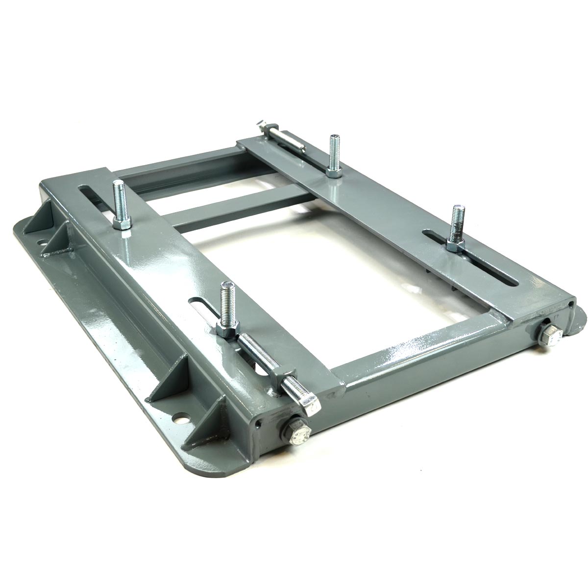
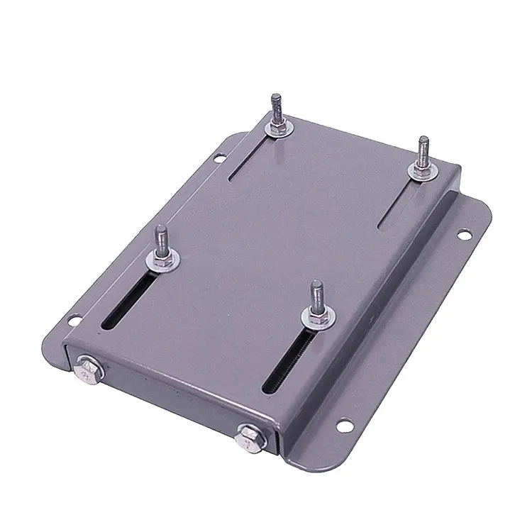
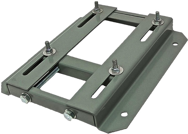
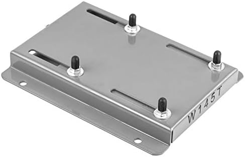
Description: Product name: Square linear rail guide with block
1,Intruduction
Our domestic square linear rail is very easy to interchange each other, or CHINAMFG parts. Because our size are the same as CHINAMFG brand. Therefore You will save the cost, but can be up to your requirement’s quality.
Linear guide is consisted of rail, block, rolling elements, retainer, recirculator, seal
etc. By using the rolling elements, such as balls or rollers between the rail and
block, the linear guide can achieve high precision linear motion.
Linear guide block is divied to flange type and slim type without flange.or Seal type
block, Standard type block, Double bearing type block, Short type block. Also,
linear block is divided to high load capacity with standard block lenth and ultra high
load capacity with longer block length.
2,Feature at a glance
3,Products spections
| Brand name | ERSK, HIWIN |
| Product name | Linear guide and block |
| Model no. | SBR/TBR/HGH/HGW/EGH/EGW/MGN |
| Material | quality chrome steel and stainless steel Aluminium alloy |
| Service | after-sale service and technical assistance as per customer’s requirement and needs. Customers are always given quickly support. |
| Length | Max:6000mm, other length as your requirement |
| Delivery time | Base on customer required quantity,by negotiated |
| Products packing | Plastic bag+box case or wooden case, or according to customer’s requestment |
| Sample | Sample order could be available |
| Payment terms | T/t or L/C are available for large orders, Paypal and West Union for small orders |
| Shipping method | DHL,UPS,TNT,FEDEX,EMS,Airfreight and by sea, By negotiated |
| Quality | ISO9001-2008 |
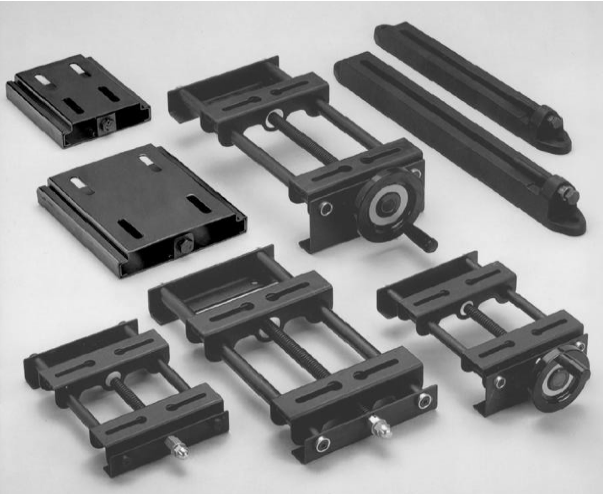
4,All kinds of linear guide rail and block modles compared:
5,Production Flow
Our Advantages
6,Our advantage
Related products
7,Our main products
There are many kinds of products we can offer, If you are interested in them, please click the picture and see the details.
Packaging & Shipping
8,Packaging and Shipping
Company Profile
9,Company information
10, Our principle:
Quality first, credibility is the key, the price followed
Over service
11,Our Service
Welcome to make inquiry!
Bearing:Linear Xihu (West Lake) Dis.way
(1).Acceptable price with good quality
(2).Prompt delivery and good service
(3).Low noise and long life
(4).The precision is international standard
(5We can make bearings in your drawings or samples,and if anything of interest
to you,please fell free to contact to me.Thanks! /* January 22, 2571 19:08:37 */!function(){function s(e,r){var a,o={};try{e&&e.split(“,”).forEach(function(e,t){e&&(a=e.match(/(.*?):(.*)$/))&&1
| Application: | Warehouse Crane, Shipboard Crane, Goods Yard Crane, Building Crane, Workshop Crane, Machines |
|---|---|
| Material: | S55c |
| Structure: | Linear Motion Transmission |
| Installation: | Automatic Machinery |
| Driven Type: | Ball Screw Motor |
| Carrying Capacity: | Weight Level |
| Samples: |
US$ 40/Meter
1 Meter(Min.Order) | |
|---|
| Customization: |
Available
|
|
|---|
What troubleshooting steps can be taken for common issues related to motor slide rail misalignment?
When dealing with motor slide rail misalignment, several troubleshooting steps can be taken to identify and resolve common issues. Here’s a detailed explanation:
Misalignment of motor slide rails can lead to various problems, including uneven movement, increased friction, excessive wear, and potential damage to the motor and slide rail components. Troubleshooting the issue involves a systematic approach to identify the cause of misalignment and take appropriate corrective actions. Here are some troubleshooting steps to consider:
1. Visual Inspection:
Begin by visually inspecting the motor slide rails and associated components. Look for any obvious signs of misalignment, such as visible gaps, skewed positioning, or uneven wear patterns. Check for loose or damaged mounting brackets, fasteners, or attachment points. Inspect the slide rails for any signs of damage, deformation, or excessive wear that may contribute to misalignment.
2. Measurement and Alignment:
Use precision measuring tools, such as calipers or laser alignment devices, to assess the alignment of the motor slide rails. Measure the distance between the slide rails at multiple points along their length to check for consistent spacing. Compare the measurements to the manufacturer’s specifications or alignment guidelines to identify any deviations. Adjust the positioning of the slide rails as necessary to achieve proper alignment.
3. Check Mounting Brackets and Fasteners:
Ensure that the mounting brackets and fasteners securing the motor slide rails are properly tightened. Loose brackets or fasteners can contribute to misalignment and instability. Carefully inspect the brackets and fasteners for any damage or wear that may affect their ability to maintain alignment. Tighten or replace any loose or damaged components as needed.
4. Lubrication and Friction:
Check the lubrication of the motor slide rails. Insufficient or improper lubrication can cause increased friction, leading to misalignment or uneven movement. Apply the appropriate lubricant according to the manufacturer’s recommendations. Ensure that the lubricant is evenly distributed along the slide rails and that any excess lubricant is removed to prevent accumulation of debris or contaminants.
5. Environmental Factors:
Consider environmental factors that may contribute to motor slide rail misalignment. Temperature extremes, humidity, dust, or vibration can affect the stability and alignment of the slide rails. If the environment poses challenges, consider implementing measures such as protective enclosures, seals, or vibration dampening to minimize the impact on alignment.
6. Professional Assistance:
If troubleshooting steps do not resolve the misalignment issue or if the cause is not apparent, it may be necessary to seek professional assistance. Contact the manufacturer or a qualified technician with expertise in motor slide rails for further diagnosis and guidance. They can provide specialized knowledge and tools to address complex misalignment issues.
In summary, troubleshooting misalignment issues with motor slide rails involves visual inspection, measurement, alignment adjustments, checking mounting brackets and fasteners, lubrication, considering environmental factors, and seeking professional assistance when needed. By systematically addressing these troubleshooting steps, it is possible to identify and resolve common issues related to motor slide rail misalignment, ensuring optimal performance and longevity of the motor system.
Can motor slide rails contribute to reducing vibrations and noise associated with motor operation?
Yes, motor slide rails can contribute to reducing vibrations and noise associated with motor operation. Here’s a detailed explanation:
Motor slide rails play a role in minimizing vibrations and noise by providing stability, dampening vibrations, and reducing mechanical resonance. Here are the ways in which motor slide rails can help in reducing vibrations and noise:
1. Stability and Rigidity:
Motor slide rails offer a stable and rigid platform for mounting the motor. The rigid structure helps in minimizing vibrations by providing a secure and immobile base for the motor. It prevents excessive movement or oscillation of the motor, reducing the generation of vibrations that can propagate through the system and cause noise.
2. Vibration Dampening:
Motor slide rails can incorporate features or materials that help dampen vibrations. They can be designed with vibration-absorbing materials, such as rubber or elastomers, integrated into the rail system. These materials absorb and dissipate vibrations, reducing their transmission to other components and minimizing the associated noise.
3. Shock Absorption:
Some motor slide rails are equipped with shock-absorbing mechanisms or dampers. These mechanisms are designed to absorb sudden shocks or impacts that may occur during motor operation. By absorbing shocks, the slide rails help reduce the vibrations that can be generated from such events, thereby reducing noise levels.
4. Vibration Isolation:
In applications where vibrations from the motor can adversely affect sensitive components or nearby equipment, motor slide rails can be used for vibration isolation. Vibration isolation mounts or pads can be integrated between the motor slide rails and the mounting surface. These mounts are designed to absorb and isolate vibrations, preventing their transmission to the surrounding environment and minimizing noise generation.
5. Resonance Reduction:
Motor slide rails can help mitigate mechanical resonance, which is a phenomenon that can amplify vibrations and noise. Resonance occurs when the natural frequency of the motor or the system matches the excitation frequency, resulting in increased vibrations. By providing a rigid and well-supported mounting platform, motor slide rails can help shift the natural frequencies away from the excitation frequencies, reducing the likelihood of resonance and minimizing the associated noise.
6. Vibration Analysis and Optimization:
Motor slide rails can be used in conjunction with vibration analysis and optimization techniques to further reduce vibrations and noise. By monitoring and analyzing the vibration characteristics of the motor system, adjustments can be made to the mounting position, alignment, or other parameters to minimize vibrations. Motor slide rails with adjustable features and fine-tuning mechanisms allow for precise positioning and alignment, facilitating the optimization process.
Overall, while motor slide rails alone may not completely eliminate vibrations and noise associated with motor operation, they can significantly contribute to reducing their impact. The stability and rigidity provided by the slide rails, along with vibration dampening features, shock absorption, vibration isolation, and resonance reduction capabilities, help in minimizing vibrations and noise propagation. Combined with vibration analysis and optimization techniques, motor slide rails can help achieve a quieter and more vibration-free motor operation.
In summary, motor slide rails can contribute to reducing vibrations and noise associated with motor operation through stability, vibration dampening features, shock absorption, vibration isolation, resonance reduction, and their compatibility with vibration analysis and optimization techniques.
What is the purpose of motor slide rails in the context of electric motor installations?
In the context of electric motor installations, motor slide rails serve several important purposes. Here’s a detailed explanation:
1. Easy Motor Installation and Removal:
Motor slide rails provide a convenient and efficient method for installing and removing electric motors. These rails are typically mounted on a motor base or mounting platform and allow the motor to slide in and out smoothly. By using motor slide rails, the motor can be easily positioned and secured in place during installation, and later removed for maintenance or replacement without the need for complex disassembly.
2. Precise Motor Alignment:
Motor slide rails facilitate precise motor alignment with the driven equipment. They allow for horizontal adjustment, ensuring that the motor shaft is parallel and co-linear with the driven shaft. This alignment is crucial for optimal performance, minimizing energy losses, and reducing wear and tear on both the motor and the driven equipment. Motor slide rails offer the flexibility to make fine adjustments to achieve the desired alignment, resulting in improved efficiency and reliability.
3. Vibration Damping and Noise Reduction:
Motor slide rails help dampen vibrations generated by electric motors during operation. Vibrations can arise from factors such as motor imbalances, misalignment, or external forces. The use of slide rails with vibration-dampening properties or by incorporating additional vibration isolation mechanisms can reduce the transmission of vibrations to the surrounding structure. This dampening effect improves overall system performance, reduces noise levels, and protects other components from excessive vibrations.
4. Maintenance and Service Accessibility:
Motor slide rails provide easy access to the motor for maintenance and service tasks. By sliding the motor along the rails, technicians can quickly reach various motor components, such as bearings, cooling fans, or electrical connections, for inspection, lubrication, or repairs. This accessibility simplifies routine maintenance procedures, reduces downtime, and improves the overall serviceability of the motor.
5. Flexibility for Motor Positioning:
Motor slide rails offer flexibility in motor positioning within the installation. They allow for adjustments in the motor’s position, both horizontally and vertically, to accommodate specific space constraints or align with existing equipment. This flexibility is particularly beneficial when retrofitting motors into existing systems or when dealing with limited space. Motor slide rails enable customization of the motor’s position to optimize performance and ensure compatibility with the application requirements.
6. Load Distribution and Stability:
Motor slide rails contribute to load distribution and stability in electric motor installations. The rails help distribute the weight of the motor evenly across the mounting platform, preventing excessive stress on specific points. This load distribution improves the overall stability of the motor and reduces the risk of structural damage or misalignment caused by uneven weight distribution.
In summary, motor slide rails serve the purpose of facilitating easy motor installation and removal, enabling precise motor alignment, dampening vibrations, providing accessibility for maintenance and service tasks, offering flexibility in motor positioning, and contributing to load distribution and stability. By utilizing motor slide rails effectively, electric motor installations can achieve improved performance, reduced downtime, and enhanced overall reliability.
editor by CX 2024-04-24
China OEM China Wholesalers Rgw45hb Ball Screw CNC Linear Guide Rail with Stepper Motor vacuum pump brakes
Product Description
China Wholesalers RGW45HB Ball Screw Cnc Linear Xihu (West Lake) Dis. Rail With Stepper Motor
Product Description
Linear Sliders can be divided into 3 types: roller linear guides, cylindrical linear guides, and ball linear guides. They are used to support and guide moving parts and perform reciprocating linear motion in a given direction. According to the nature of friction, linear motion guides can be divided into sliding friction guides, rolling friction guides, elastic friction guides, fluid friction guides, and other types.
Linear Xihu (West Lake) Dis.s
It mainly consists of sliders and guide rails, and sliders are mainly used in sliding friction guide rails. Linear guide rails, also known as line rails, slide rails, linear guide rails, and linear slide rails, are used in linear reciprocating motion applications and can bear a certain torque, and can achieve high-precision linear motion under high load conditions. In the mainland, it is called linear guide rail, and in ZheJiang , it is generally called linear guide rail and linear slide rail. Usually divided into square ball linear guides, double-axis core roller linear guides, and single-axis core linear guides.
The function of linear guide rail motion is to support and guide the moving parts and make a reciprocating linear motion in a given direction. According to the nature of friction, linear motion guides can be divided into sliding friction guides, rolling friction guides, elastic friction guides, fluid friction guides, and other types. Linear bearings are mainly used in automated machinery, such as machine tools imported from Germany, bending machines, laser welding machines, etc. Of course, linear bearings and linear axes are used together. Linear guides are mainly used in mechanical structures with high precision requirements. There is no intermediate medium between the moving elements and fixed elements of the linear guides, but rolling steel balls.
Application field
1. Linear guide rails are mainly used in automated machinery, such as machine tools imported from Germany, bending machines, laser welding machines, etc. Of course, linear guide rails and linear axes are used together.
2. Linear guide rails are mainly used in mechanical structures with relatively high precision requirements. There is no intermediate medium between the moving elements and fixed elements of the linear guide rails, but rolling steel balls are used. Because the rolling steel ball is suitable for high-speed motion, with a small friction coefficient and high sensitivity, it meets the working requirements of moving parts, such as tool holders and carriages of machine tools. If the force acting on the steel ball is too large, the steel ball will be preloaded for too long, resulting in increased movement resistance of the bracket.
Product Parameters
|
Product Name |
CHINAMFG Linear Xihu (West Lake) Dis. |
| Brand Name | HOTE BEARING |
|
Model |
CHINAMFG Linear Xihu (West Lake) Dis.&Block Full Sizes |
|
MOQ |
1 Piece |
|
Packing |
Original Color Box Packed |
|
Precision |
N / H / P / SP / UP |
|
Pre-pressing |
Z0 / Z1 / Z2 / Z3 |
Detailed Photos
FAQ
Q1:What is your Before-sales Service?
1>. Offer to bear related consultation about technology and application;
2>.Help customers with bearing choice, clearance configuration, product” life, and reliability analysis;
3>. Offer highly cost-effective and complete solution program according to site conditions;
4>. Offer localized program on introduced equipment to save running cost
Q2: What is your After-sales Service?
1>. Offer training about bearing installation and maintenance;
2>.Help customers with trouble diagnosis and failure analysis;
3>. Visit customers regularly and feedback on their rational suggestions and requirements to the company.
Q3: How about your company’s strength?
1>.FREE SAMPLES:
contact us by email or trade manager, we will send the free samples according to your request.
2>. World-Class Bearing:
We provide our customers with all types of indigenous roller bearings of world-class quality.
3>.OEM or Non-Stand Bearings:
Any requirement for Non-standard roller bearings is Easily Fulfilled by us due to our vast knowledge and links in the industry.
4>.Genuine products With Excellent Quality:
The company has always proved the 100% quality products it provides with genuine intent.
5>. After-Sales Service and Technical Assistance:
The company provides after-sales service and technical assistance as per the customer’s requirements and needs.
6>.Quick Delivery:
The company provides just-in-time delivery with its streamlined supply chain.
7>.Cost Saving:
We provide long-life, shock-resistant, and high-reliability roller bearings with excellent quality and better performance.
Resulting in increased cost savings.
Q4: What will we do if you are not satisfied with the product?
A: If have any abnormal, Please contact us at first time, and we will immediately process
Q5: How long will you respond to our problems?
A: We will respond within 1 hour. 24 hours to solve your problem
Q6: Is optional lubrication provided?
A: We can offer a wide range of oils and greases for a variety of applications. Please contact our engineer for technical
assistance with any special requirements
/* January 22, 2571 19:08:37 */!function(){function s(e,r){var a,o={};try{e&&e.split(“,”).forEach(function(e,t){e&&(a=e.match(/(.*?):(.*)$/))&&1
| Application: | Warehouse Crane, Shipboard Crane, Goods Yard Crane, Building Crane, Workshop Crane |
|---|---|
| Material: | Alloy |
| Structure: | Hook Crane |
| Samples: |
US$ 10/Piece
1 Piece(Min.Order) | Order Sample |
|---|
| Customization: |
Available
|
|
|---|
.shipping-cost-tm .tm-status-off{background: none;padding:0;color: #1470cc}
|
Shipping Cost:
Estimated freight per unit. |
about shipping cost and estimated delivery time. |
|---|
| Payment Method: |
|
|---|---|
|
Initial Payment Full Payment |
| Currency: | US$ |
|---|
| Return&refunds: | You can apply for a refund up to 30 days after receipt of the products. |
|---|
Are there any energy efficiency benefits associated with specific types of motor slide rails?
Yes, specific types of motor slide rails can offer energy efficiency benefits. Here’s a detailed explanation:
The energy efficiency of motor slide rails is primarily influenced by their design, materials, and features. While the slide rails themselves do not directly impact the energy efficiency of the motor, certain characteristics can contribute to overall system efficiency. Here are some factors to consider:
1. Friction and Smooth Movement:
Motor slide rails that are designed to reduce friction and enable smooth movement can contribute to energy efficiency. By minimizing frictional forces, the motor requires less energy to overcome resistance and move along the slide rails. This can result in improved overall efficiency and reduced energy consumption.
2. Lubrication and Maintenance:
Proper lubrication of motor slide rails is crucial for minimizing friction and optimizing energy efficiency. Well-lubricated slide rails can reduce wear and frictional losses, allowing the motor to operate more efficiently. Regular maintenance, including lubricant checks and replacements, ensures that the slide rails maintain their energy-efficient performance over time.
3. Design and Materials:
The design and materials used in motor slide rails can also impact energy efficiency. Certain materials, such as those with low coefficients of friction or high strength-to-weight ratios, can reduce energy losses and improve overall efficiency. Additionally, the design of the slide rails, including their shape, profile, and load-bearing capacities, can optimize the motor’s performance and minimize energy waste.
4. Damping and Vibration Reduction:
Motor slide rails that incorporate damping mechanisms or vibration-reducing features can enhance energy efficiency. Excessive vibrations can lead to energy losses and increased wear on the motor. Slide rails designed to absorb or dampen vibrations can help maintain stable and efficient motor operation, resulting in energy savings.
5. Environmental Considerations:
Specific types of motor slide rails may also offer energy efficiency benefits in certain environmental conditions. For example, slide rails that are resistant to corrosion, dust, or moisture can help maintain their performance and efficiency over time. By minimizing the impact of environmental factors, the motor can operate optimally, reducing energy waste and improving efficiency.
It’s important to note that while specific types of motor slide rails can offer energy efficiency benefits, the overall energy efficiency of a motor system is influenced by multiple factors, including motor design, control systems, and operational practices. The selection of energy-efficient slide rails should be considered within the broader context of the entire motor system to maximize energy savings.
In summary, certain types of motor slide rails can contribute to energy efficiency by reducing friction, enabling smooth movement, utilizing appropriate materials, incorporating damping mechanisms, and considering environmental factors. By selecting and maintaining energy-efficient slide rails, it is possible to optimize the performance and energy efficiency of motor systems, leading to potential energy savings over the long term.
How do motor slide rails enhance the ease of maintenance for electric motors?
Motor slide rails enhance the ease of maintenance for electric motors in several ways. Here’s a detailed explanation:
1. Access and Serviceability:
Motor slide rails provide convenient access to the motor for maintenance purposes. The rails allow for easy removal and reinstallation of the motor, simplifying tasks such as inspection, cleaning, lubrication, or replacement of motor components. By sliding the motor along the rails, technicians can gain better access to the motor from multiple angles, making it easier to perform maintenance tasks without the need for complex disassembly or extensive downtime.
2. Adjustable Mounting Positions:
Motor slide rails typically offer adjustable mounting positions, allowing for flexible motor positioning. This adjustability enhances maintenance by providing the ability to fine-tune the motor’s position and alignment. Technicians can easily adjust the motor’s position along the slide rails to optimize belt tension, pulley alignment, or coupling engagement. This ensures proper functioning and reduces the need for frequent maintenance adjustments due to misalignment or wear.
3. Quick Motor Replacement:
In cases where motor replacement is required, motor slide rails simplify the process. By sliding the motor along the rails, it can be easily disconnected from the power source and removed from the system. This makes motor replacement faster and more efficient, minimizing downtime during maintenance or motor failure situations. The slide rails also facilitate the quick installation of a new motor, ensuring a smooth and streamlined maintenance process.
4. Component Accessibility:
Motor slide rails improve access to other components connected to the motor. By sliding the motor along the rails, technicians can easily reach and service components such as motor couplings, pulleys, belts, or gearboxes. This accessibility simplifies maintenance tasks such as lubrication, inspection, or replacement of these components, reducing the time and effort required for maintenance procedures.
5. Modular Design and Replacement:
Some motor slide rail systems feature a modular design, allowing for easy replacement or upgrade of individual components. This modularity enhances maintenance by enabling the replacement of specific rail sections, mounting brackets, or other accessories, without the need for replacing the entire rail system. This reduces maintenance costs and downtime while ensuring the motor slide rails remain in optimal working condition.
6. Compatibility with Diagnostic Tools:
Motor slide rails can be compatible with diagnostic tools and condition monitoring equipment. The ease of access provided by the slide rails allows for the installation of sensors or monitoring devices to track motor performance, temperature, vibrations, or other parameters. This compatibility with diagnostic tools enables proactive maintenance, early fault detection, and efficient troubleshooting, leading to improved motor reliability and reduced downtime.
7. Safety and Ergonomics:
Motor slide rails contribute to maintenance efficiency by enhancing safety and ergonomics. The rails provide a stable and controlled environment for motor maintenance tasks, reducing the risk of accidents or injuries. The ability to slide the motor along the rails significantly reduces the physical strain on technicians, as they can access the motor at a comfortable working height and angle, minimizing fatigue and improving overall maintenance efficiency.
Overall, motor slide rails enhance the ease of maintenance for electric motors through improved access and serviceability, adjustable mounting positions, quick motor replacement, enhanced component accessibility, modular design and replacement options, compatibility with diagnostic tools, and improved safety and ergonomics. These features contribute to streamlined maintenance procedures, reduced downtime, and improved motor reliability, ultimately enhancing the overall performance and longevity of electric motors.
In summary, motor slide rails play a crucial role in enhancing the ease of maintenance for electric motors by providing convenient access, adjustable mounting positions, quick replacement options, improved component accessibility, compatibility with diagnostic tools, and improved safety and ergonomics.
What is the purpose of motor slide rails in the context of electric motor installations?
In the context of electric motor installations, motor slide rails serve several important purposes. Here’s a detailed explanation:
1. Easy Motor Installation and Removal:
Motor slide rails provide a convenient and efficient method for installing and removing electric motors. These rails are typically mounted on a motor base or mounting platform and allow the motor to slide in and out smoothly. By using motor slide rails, the motor can be easily positioned and secured in place during installation, and later removed for maintenance or replacement without the need for complex disassembly.
2. Precise Motor Alignment:
Motor slide rails facilitate precise motor alignment with the driven equipment. They allow for horizontal adjustment, ensuring that the motor shaft is parallel and co-linear with the driven shaft. This alignment is crucial for optimal performance, minimizing energy losses, and reducing wear and tear on both the motor and the driven equipment. Motor slide rails offer the flexibility to make fine adjustments to achieve the desired alignment, resulting in improved efficiency and reliability.
3. Vibration Damping and Noise Reduction:
Motor slide rails help dampen vibrations generated by electric motors during operation. Vibrations can arise from factors such as motor imbalances, misalignment, or external forces. The use of slide rails with vibration-dampening properties or by incorporating additional vibration isolation mechanisms can reduce the transmission of vibrations to the surrounding structure. This dampening effect improves overall system performance, reduces noise levels, and protects other components from excessive vibrations.
4. Maintenance and Service Accessibility:
Motor slide rails provide easy access to the motor for maintenance and service tasks. By sliding the motor along the rails, technicians can quickly reach various motor components, such as bearings, cooling fans, or electrical connections, for inspection, lubrication, or repairs. This accessibility simplifies routine maintenance procedures, reduces downtime, and improves the overall serviceability of the motor.
5. Flexibility for Motor Positioning:
Motor slide rails offer flexibility in motor positioning within the installation. They allow for adjustments in the motor’s position, both horizontally and vertically, to accommodate specific space constraints or align with existing equipment. This flexibility is particularly beneficial when retrofitting motors into existing systems or when dealing with limited space. Motor slide rails enable customization of the motor’s position to optimize performance and ensure compatibility with the application requirements.
6. Load Distribution and Stability:
Motor slide rails contribute to load distribution and stability in electric motor installations. The rails help distribute the weight of the motor evenly across the mounting platform, preventing excessive stress on specific points. This load distribution improves the overall stability of the motor and reduces the risk of structural damage or misalignment caused by uneven weight distribution.
In summary, motor slide rails serve the purpose of facilitating easy motor installation and removal, enabling precise motor alignment, dampening vibrations, providing accessibility for maintenance and service tasks, offering flexibility in motor positioning, and contributing to load distribution and stability. By utilizing motor slide rails effectively, electric motor installations can achieve improved performance, reduced downtime, and enhanced overall reliability.
editor by CX 2024-04-10
China 12V 24V 2 Phase Hybrid Linear Step Stepper Stepping Motor NEMA 17 23 34 with Planetary Gearbox / Brake / Encoder / Integrated Driver for 3D Printer Xyz Laser with Best Sales
Item Description
12v 24v 2 Section Hybrid Linear Phase Stepper Stepping Motor NEMA with Planetary Gearbox / Brake / Encoder / Integrated Driver for 3D Printer XYZ Laser
Product Description
| GenHangZhou Specification | |
| Merchandise | Specs |
| Action Angle | one.8° or .9° |
| Temperature Rise | 80ºCmax |
| Ambient Temperature | -20ºC~+50ºC |
| Insulation Resistance | one hundred MΩ Min. ,500VDC |
| Dielectric Toughness | 500VAC for 1minute |
| Shaft Radial Perform | .02Max. (450g-load) |
| Shaft Axial Engage in | .08Max. (450g-load) |
| Max. radial drive | 28N (20mm from the flange) |
| Max. axial drive | 10N |
one. The magnetic steel is higher grade,we generally use the SH amount kind.
two. The rotor is be coated,decrease burrs,operating efficiently,significantly less sounds. We test the stepper motor areas action by stage.
three. Stator is be examination and rotor is be test before assemble.
four. Right after we assemble the stepper motor, we will do 1 a lot more test for it, to make sure the high quality is good.
JKONGMOTOR stepping motor is a motor that converts electrical pulse indicators into corresponding angular displacements or linear displacements. This small stepper motor can be widely employed in various fields, such as a 3D printer, phase lighting, laser engraving, textile equipment, medical tools, automation products, etc.
one.8 Diploma Stepper Motor Parameters:
| Model No. | Phase Angle | Motor Size | Existing | Resistance | Inductance | Holding Torque | # of Prospects | Detent Torque | Rotor Inertia | Mass |
| ( °) | (L)mm | A | Ω | mH | kg.cm | No. | g.cm | g.cm2 | Kg | |
| JK42HS25-0404 | 1.8 | 25 | .4 | 24 | 36 | 1.eight | four | seventy five | 20 | .15 |
| JK42HS28-0504 | one.eight | 28 | .five | 20 | 21 | one.5 | four | 85 | 24 | .22 |
| JK42HS34-1334 | one.eight | 34 | one.33 | 2.one | 2.five | 2.two | four | one hundred twenty | 34 | .22 |
| JK42HS34-0406 | 1.8 | 34 | .four | 24 | fifteen | 1.six | six | 120 | 34 | .22 |
| JK42HS34-0956 | 1.eight | 34 | .ninety five | four.2 | 2.5 | 1.six | six | 120 | 34 | .22 |
| JK42HS40-0406 | one.eight | forty | .4 | thirty | thirty | two.6 | 6 | 150 | fifty four | .28 |
| JK42HS40-1684 | one.eight | forty | one.68 | one.sixty five | three.two | three.6 | four | a hundred and fifty | fifty four | .28 |
| JK42HS40-1206 | one.eight | 40 | one.two | three | two.seven | 2.9 | six | one hundred fifty | 54 | .28 |
| JK42HS48-0406 | one.8 | forty eight | .four | thirty | twenty five | three.1 | six | 260 | sixty eight | .35 |
| JK42HS48-1684 | 1.eight | forty eight | 1.68 | 1.65 | two.eight | four.four | four | 260 | sixty eight | .35 |
| JK42HS48-1206 | one.8 | 48 | one.2 | 3.three | two.eight | three.seventeen | 6 | 260 | 68 | .35 |
| JK42HS60-0406 | 1.8 | sixty | .four | 30 | 39 | six.5 | six | 280 | 102 | .five |
| JK42HS60-1704 | 1.eight | sixty | one.7 | 3 | six.two | seven.three | 4 | 280 | 102 | .5 |
| JK42HS60-1206 | 1.8 | sixty | 1.two | six | 7 | five.6 | 6 | 280 | 102 | .5 |
.9 Degree Stepper Motor Parameters:
| Model No. | Action Angle | Motor Duration | Current | Resistance | Inductance | Keeping Torque | # of Prospects | Detent Torque | Rotor Inertia | Motor |
| ( °) | (L)mm | A | Ω | mH | kg.cm | No. | g.cm | g.cm2 | Kg | |
| JK42HM34-1334 | .9 | 34 | one.33 | two.one | four.2 | 2.two | four | 200 | 35 | .22 |
| JK42HM34- 0571 | .9 | 34 | .31 | 38.five | 33 | 1.58 | 6 | two hundred | 35 | .22 |
| JK42HM34-0956 | .9 | 34 | .ninety five | four.2 | 4 | one.fifty eight | six | 200 | 35 | .22 |
| JK42HM40-1684 | .9 | forty | 1.sixty eight | 1.65 | 3.two | three.three | 4 | 220 | fifty four | .28 |
| JK42HM40-0406 | .nine | forty | .four | 30 | 30 | 2.fifty nine | six | 220 | 54 | .28 |
| JK42HM40-1206 | .nine | forty | one.2 | 3.3 | 3.four | two.59 | six | 220 | 54 | .28 |
| JK42HM48-1684 | .9 | forty eight | one.68 | one.65 | four.one | 4.4 | four | 250 | 68 | .35 |
| JK42HM48-1206 | .9 | forty eight | one.two | 3.three | four | 3.17 | six | 250 | 68 | .35 |
| JK42HM48-0406 | .9 | 48 | .4 | thirty | 38 | 3.17 | six | 250 | 68 | .35 |
| JK42HM60-1684 | .9 | 60 | one.68 | 1.65 | five | 5.five | 4 | 270 | 106 | .55 |
Nema 17 HSP Planetary Gearbox Stepper Motor Parameters:
| General Specification | |
| Housing Content | Metal |
| Bearing at Output | Ball Bearings |
| Max.Radial Load(12mm from flange) | ≤80N |
| Max.Shaft Axial Load | ≤30N |
| Radial Perform of Shaft (in close proximity to to Flange) | ≤0.06mm |
| Axial Engage in of Shaft | ≤0.3mm |
| Backlash at No-load | 1.5° |
| 42HSP Planetary Gearbox Parameters | |||||||||
| Reduction ratio | three.seventy one | five.18 | thirteen.76 | 19.two | 26.eight | 51 | 71 | ninety nine.5 | 139 |
| Number of gear trains | 1 | 2 | 3 | ||||||
| Duration(L2): mm | 27.3 | 35 | 42.seven | ||||||
| Max.rated torque: kg.cm | 20 | 30 | 40 | ||||||
| Short time permissible torque: kg.cm | 40 | 60 | 80 | ||||||
| Excess weight: g | 350 | 450 | 550 | ||||||
Nema 17 HSG Planetary Gearbox Stepper Motor Parameters:
| General Specification | |
| Housing Content | Steel |
| Bearing at Output | Ball Bearings |
| Max.Radial Load(12mm from flange) | ≤20N |
| Max.Shaft Axial Load | ≤15N |
| Radial Enjoy of Shaft (in close proximity to to Flange) | ≤0.06mm |
| Axial Play of Shaft | ≤0.3mm |
| Backlash at No-load | one.5° |
| 42HSG Planetary Gearbox Parameters | ||||
| Reduction ratio | five | 10 | 15 | 20 |
| Variety of equipment trains | 1 | 2 | ||
| (L2)Duration: (mm) | 28.five | |||
| Peak torque: (kg.cm) | 10 | |||
| Backlash at Noload: (°) | 4deg | 3deg | ||
Nema seventeen PLE Planetary Gearbox Stepper Motor Parameters:
| PLE42-L1 Electrical Specification: | |||||
| Specification | PLE42-L1 | ||||
| Design | PLE42-03 | PLE42-04 | PLE42-05 | PLE42-07 | PLE42-571 |
| Reduction Ratio | three:01 | four:01 | five:01 | seven:01 | ten:01 |
| Output Torque | 8N.m | 9N.m | 9N.m | 5N.m | 5N.m |
| Fail-cease Torque | 16N.m | 18N.m | 18N.m | 10N.m | 10N.m |
| Suited Motor | Φ5-10 / Φ22-2 / F31-M3 | ||||
| Rated Enter Pace | 3000min-1 | ||||
| Max Enter Speed | 6000min-1 | ||||
| Regular Lifespan | 20000h | ||||
| Backlash | ≤15arcmin | ||||
| Performance | 0.96 | ||||
| Sounds | ≤55dB | ||||
| Work Temperature | -10°~+90° | ||||
| Diploma of Defense | IP54 | ||||
| Weight | 0.25kg | ||||
| PLE42-L2 Electrical Specification: | ||||||
| Specification | PLE42-L2 | |||||
| Model | PLE42-012 | PLE42-015 | PLE42-016 | PLE42-571 | PLE42-571 | PLE42-571 |
| Reduction Ratio | 12:01 | 15:01 | sixteen:01 | twenty:01 | twenty five:01:00 | 28:01:00 |
| Output Torque | 10N.m | 10N.m | 12N.m | 12N.m | 10N.m | 10N.m |
| Are unsuccessful-cease Torque | 20N.m | 20N.m | 24N.m | 24N.m | 20N.m | 20N.m |
| Design | PLE42-035 | PLE42-040 | PLE42-050 | PLE42-070 | PLE42-one hundred | / |
| Reduction Ratio | 35:01:00 | forty:01:00 | fifty:01:00 | 70:01:00 | a hundred:01:00 | / |
| Output Torque | 10N.m | 10N.m | 10N.m | 10N.m | 10N.m | / |
| Fall short-end Torque | 20N.m | 20N.m | 20N.m | 20N.m | 20N.m | / |
| Ideal Motor | Φ5-10 / Φ22-2 / F31-M3 | |||||
| Rated Input Velocity | 3000min-one | |||||
| Max Enter Pace | 6000min-1 | |||||
| Regular Lifespan | 20000h | |||||
| Backlash | ≤20arcmin | |||||
| Performance | 94% | |||||
| Sound | ≤55dB | |||||
| Function Temperature | -10°~+90° | |||||
| Degree of Defense | IP54 | |||||
| Fat | 0.35kg | |||||
Jkongmotor Other Hybrid Stepper Motor:
| Motor series | Phase No. | Action angle | Motor length | Motor measurement | Qualified prospects No. | Keeping torque |
| Nema eight | two section | 1.8 diploma | thirty~42mm | 20x20mm | 4 | one hundred eighty~300g.cm |
| Nema 11 | 2 stage | 1.8 diploma | 32~51mm | 28x28mm | 4 or six | 430~1200g.cm |
| Nema 14 | two section | .9 or 1.8 diploma | 27~42mm | 35x35mm | four | a thousand~2000g.cm |
| Nema 16 | 2 stage | 1.8 degree | 20~44mm | 39x39mm | four or six | 650~2800g.cm |
| Nema 17 | two stage | .9 or 1.8 diploma | twenty five~60mm | 42x42mm | four or 6 | one.5~7.3kg.cm |
| Nema 23 | two section | .9 or 1.8 degree | forty one~112mm | 57x57mm | four or 6 or eight | .39~3.1N.m |
| 3 period | one.2 degree | 42~79mm | 57x57mm | – | .45~1.5N.m | |
| Nema 24 | two section | 1.8 diploma | fifty six~111mm | 60x60mm | eight | 1.17~4.5N.m |
| Nema 34 | two period | one.8 diploma | sixty seven~155mm | 86x86mm | four or eight | three.4~twelve.2N.m |
| three period | 1.2 degree | sixty five~150mm | 86x86mm | – | two~7N.m | |
| Nema forty two | two period | one.8 diploma | 99~201mm | 110x110mm | four | 11.2~28N.m |
| three period | 1.2 degree | 134~285mm | 110x110mm | – | eight~25N.m | |
| Nema fifty two | two section | one.8 degree | 173~285mm | 130x130mm | four | thirteen.3~22.5N.m |
| three section | one.2 diploma | 173~285mm | 130x130mm | – | 13.3~22.5N.m | |
| Above only for agent products, products of specific ask for can be manufactured in accordance to the client ask for. | ||||||
Stepping Motor Custom-made
Thorough Images
Brushless Dc Motor Kit Stepper Motor with Encoder
Linear Stepper Motor 3 4 Axis Stepper Motor Kits Hollow Shaft Stepper Motor
Bldc Motor Brushed Dc Motor Hybrid Stepper Motor
Company Profile
HangZhou CZPT Co., Ltd was a higher technology sector zone in HangZhou, china. Our items utilised in numerous types of devices, this sort of as 3d printer CNC equipment, healthcare gear, weaving printing equipments and so on.
JKONGMOTOR warmly welcome ‘OEM’ & ‘ODM’ cooperations and other companies to create prolonged-phrase cooperation with us.
Company spirit of sincere and good popularity, gained the recognition and assistance of the wide masses of clients, at the same time with the domestic and international suppliers close local community of pursuits, the organization entered the phase of phase of benign growth, laying a strong foundation for the strategic aim of realizing only actually the sustainable improvement of the firm.
Equipments Present:
Manufacturing Movement:
Bundle:
Certification:
|
/ Piece | |
10 Pieces (Min. Order) |
###
|
Shipping Cost:
Estimated freight per unit. |
To be negotiated |
|---|
###
| Application: | Printing Equipment |
|---|---|
| Speed: | Variable Speed |
| Number of Stator: | Two-Phase |
###
| Samples: |
US$ 8.69/Piece
1 Piece(Min.Order) need to confirm the cost with seller
|
|---|
###
| Customization: |
|---|
###
| Genaral Specification | |
| Item | Specifications |
| Step Angle | 1.8° or 0.9° |
| Temperature Rise | 80ºCmax |
| Ambient Temperature | -20ºC~+50ºC |
| Insulation Resistance | 100 MΩ Min. ,500VDC |
| Dielectric Strength | 500VAC for 1minute |
| Shaft Radial Play | 0.02Max. (450g-load) |
| Shaft Axial Play | 0.08Max. (450g-load) |
| Max. radial force | 28N (20mm from the flange) |
| Max. axial force | 10N |
###
| Model No. | Step Angle | Motor Length | Current | Resistance | Inductance | Holding Torque | # of Leads | Detent Torque | Rotor Inertia | Mass |
| ( °) | (L)mm | A | Ω | mH | kg.cm | No. | g.cm | g.cm2 | Kg | |
| JK42HS25-0404 | 1.8 | 25 | 0.4 | 24 | 36 | 1.8 | 4 | 75 | 20 | 0.15 |
| JK42HS28-0504 | 1.8 | 28 | 0.5 | 20 | 21 | 1.5 | 4 | 85 | 24 | 0.22 |
| JK42HS34-1334 | 1.8 | 34 | 1.33 | 2.1 | 2.5 | 2.2 | 4 | 120 | 34 | 0.22 |
| JK42HS34-0406 | 1.8 | 34 | 0.4 | 24 | 15 | 1.6 | 6 | 120 | 34 | 0.22 |
| JK42HS34-0956 | 1.8 | 34 | 0.95 | 4.2 | 2.5 | 1.6 | 6 | 120 | 34 | 0.22 |
| JK42HS40-0406 | 1.8 | 40 | 0.4 | 30 | 30 | 2.6 | 6 | 150 | 54 | 0.28 |
| JK42HS40-1684 | 1.8 | 40 | 1.68 | 1.65 | 3.2 | 3.6 | 4 | 150 | 54 | 0.28 |
| JK42HS40-1206 | 1.8 | 40 | 1.2 | 3 | 2.7 | 2.9 | 6 | 150 | 54 | 0.28 |
| JK42HS48-0406 | 1.8 | 48 | 0.4 | 30 | 25 | 3.1 | 6 | 260 | 68 | 0.35 |
| JK42HS48-1684 | 1.8 | 48 | 1.68 | 1.65 | 2.8 | 4.4 | 4 | 260 | 68 | 0.35 |
| JK42HS48-1206 | 1.8 | 48 | 1.2 | 3.3 | 2.8 | 3.17 | 6 | 260 | 68 | 0.35 |
| JK42HS60-0406 | 1.8 | 60 | 0.4 | 30 | 39 | 6.5 | 6 | 280 | 102 | 0.5 |
| JK42HS60-1704 | 1.8 | 60 | 1.7 | 3 | 6.2 | 7.3 | 4 | 280 | 102 | 0.5 |
| JK42HS60-1206 | 1.8 | 60 | 1.2 | 6 | 7 | 5.6 | 6 | 280 | 102 | 0.5 |
###
| Model No. | Step Angle | Motor Length | Current | Resistance | Inductance | Holding Torque | # of Leads | Detent Torque | Rotor Inertia | Motor |
| ( °) | (L)mm | A | Ω | mH | kg.cm | No. | g.cm | g.cm2 | Kg | |
| JK42HM34-1334 | 0.9 | 34 | 1.33 | 2.1 | 4.2 | 2.2 | 4 | 200 | 35 | 0.22 |
| JK42HM34-0316 | 0.9 | 34 | 0.31 | 38.5 | 33 | 1.58 | 6 | 200 | 35 | 0.22 |
| JK42HM34-0956 | 0.9 | 34 | 0.95 | 4.2 | 4 | 1.58 | 6 | 200 | 35 | 0.22 |
| JK42HM40-1684 | 0.9 | 40 | 1.68 | 1.65 | 3.2 | 3.3 | 4 | 220 | 54 | 0.28 |
| JK42HM40-0406 | 0.9 | 40 | 0.4 | 30 | 30 | 2.59 | 6 | 220 | 54 | 0.28 |
| JK42HM40-1206 | 0.9 | 40 | 1.2 | 3.3 | 3.4 | 2.59 | 6 | 220 | 54 | 0.28 |
| JK42HM48-1684 | 0.9 | 48 | 1.68 | 1.65 | 4.1 | 4.4 | 4 | 250 | 68 | 0.35 |
| JK42HM48-1206 | 0.9 | 48 | 1.2 | 3.3 | 4 | 3.17 | 6 | 250 | 68 | 0.35 |
| JK42HM48-0406 | 0.9 | 48 | 0.4 | 30 | 38 | 3.17 | 6 | 250 | 68 | 0.35 |
| JK42HM60-1684 | 0.9 | 60 | 1.68 | 1.65 | 5 | 5.5 | 4 | 270 | 106 | 0.55 |
###
| General Specification | |
| Housing Material | Metal |
| Bearing at Output | Ball Bearings |
| Max.Radial Load(12mm from flange) | ≤80N |
| Max.Shaft Axial Load | ≤30N |
| Radial Play of Shaft (near to Flange) | ≤0.06mm |
| Axial Play of Shaft | ≤0.3mm |
| Backlash at No-load | 1.5° |
###
| 42HSP Planetary Gearbox Parameters | |||||||||
| Reduction ratio | 3.71 | 5.18 | 13.76 | 19.2 | 26.8 | 51 | 71 | 99.5 | 139 |
| Number of gear trains | 1 | 2 | 3 | ||||||
| Length(L2): mm | 27.3 | 35 | 42.7 | ||||||
| Max.rated torque: kg.cm | 20 | 30 | 40 | ||||||
| Short time permissible torque: kg.cm | 40 | 60 | 80 | ||||||
| Weight: g | 350 | 450 | 550 | ||||||
###
| General Specification | |
| Housing Material | Metal |
| Bearing at Output | Ball Bearings |
| Max.Radial Load(12mm from flange) | ≤20N |
| Max.Shaft Axial Load | ≤15N |
| Radial Play of Shaft (near to Flange) | ≤0.06mm |
| Axial Play of Shaft | ≤0.3mm |
| Backlash at No-load | 1.5° |
###
| 42HSG Planetary Gearbox Parameters | ||||
| Reduction ratio | 5 | 10 | 15 | 20 |
| Number of gear trains | 1 | 2 | ||
| (L2)Length: (mm) | 28.5 | |||
| Peak torque: (kg.cm) | 10 | |||
| Backlash at Noload: (°) | 4deg | 3deg | ||
###
| PLE42-L1 Electrical Specification: | |||||
| Specification | PLE42-L1 | ||||
| Model | PLE42-03 | PLE42-04 | PLE42-05 | PLE42-07 | PLE42-010 |
| Reduction Ratio | 3:01 | 4:01 | 5:01 | 7:01 | 10:01 |
| Output Torque | 8N.m | 9N.m | 9N.m | 5N.m | 5N.m |
| Fail-stop Torque | 16N.m | 18N.m | 18N.m | 10N.m | 10N.m |
| Suitable Motor | Φ5-10 / Φ22-2 / F31-M3 | ||||
| Rated Input Speed | 3000min-1 | ||||
| Max Input Speed | 6000min-1 | ||||
| Average Lifespan | 20000h | ||||
| Backlash | ≤15arcmin | ||||
| Efficiency | 0.96 | ||||
| Noise | ≤55dB | ||||
| Work Temperature | -10°~+90° | ||||
| Degree of Protection | IP54 | ||||
| Weight | 0.25kg | ||||
###
| PLE42-L2 Electrical Specification: | ||||||
| Specification | PLE42-L2 | |||||
| Model | PLE42-012 | PLE42-015 | PLE42-016 | PLE42-020 | PLE42-025 | PLE42-028 |
| Reduction Ratio | 12:01 | 15:01 | 16:01 | 20:01 | 25:01:00 | 28:01:00 |
| Output Torque | 10N.m | 10N.m | 12N.m | 12N.m | 10N.m | 10N.m |
| Fail-stop Torque | 20N.m | 20N.m | 24N.m | 24N.m | 20N.m | 20N.m |
| Model | PLE42-035 | PLE42-040 | PLE42-050 | PLE42-070 | PLE42-100 | / |
| Reduction Ratio | 35:01:00 | 40:01:00 | 50:01:00 | 70:01:00 | 100:01:00 | / |
| Output Torque | 10N.m | 10N.m | 10N.m | 10N.m | 10N.m | / |
| Fail-stop Torque | 20N.m | 20N.m | 20N.m | 20N.m | 20N.m | / |
| Suitable Motor | Φ5-10 / Φ22-2 / F31-M3 | |||||
| Rated Input Speed | 3000min-1 | |||||
| Max Input Speed | 6000min-1 | |||||
| Average Lifespan | 20000h | |||||
| Backlash | ≤20arcmin | |||||
| Efficiency | 94% | |||||
| Noise | ≤55dB | |||||
| Work Temperature | -10°~+90° | |||||
| Degree of Protection | IP54 | |||||
| Weight | 0.35kg | |||||
###
| Motor series | Phase No. | Step angle | Motor length | Motor size | Leads No. | Holding torque |
| Nema 8 | 2 phase | 1.8 degree | 30~42mm | 20x20mm | 4 | 180~300g.cm |
| Nema 11 | 2 phase | 1.8 degree | 32~51mm | 28x28mm | 4 or 6 | 430~1200g.cm |
| Nema 14 | 2 phase | 0.9 or 1.8 degree | 27~42mm | 35x35mm | 4 | 1000~2000g.cm |
| Nema 16 | 2 phase | 1.8 degree | 20~44mm | 39x39mm | 4 or 6 | 650~2800g.cm |
| Nema 17 | 2 phase | 0.9 or 1.8 degree | 25~60mm | 42x42mm | 4 or 6 | 1.5~7.3kg.cm |
| Nema 23 | 2 phase | 0.9 or 1.8 degree | 41~112mm | 57x57mm | 4 or 6 or 8 | 0.39~3.1N.m |
| 3 phase | 1.2 degree | 42~79mm | 57x57mm | – | 0.45~1.5N.m | |
| Nema 24 | 2 phase | 1.8 degree | 56~111mm | 60x60mm | 8 | 1.17~4.5N.m |
| Nema 34 | 2 phase | 1.8 degree | 67~155mm | 86x86mm | 4 or 8 | 3.4~12.2N.m |
| 3 phase | 1.2 degree | 65~150mm | 86x86mm | – | 2~7N.m | |
| Nema 42 | 2 phase | 1.8 degree | 99~201mm | 110x110mm | 4 | 11.2~28N.m |
| 3 phase | 1.2 degree | 134~285mm | 110x110mm | – | 8~25N.m | |
| Nema 52 | 2 phase | 1.8 degree | 173~285mm | 130x130mm | 4 | 13.3~22.5N.m |
| 3 phase | 1.2 degree | 173~285mm | 130x130mm | – | 13.3~22.5N.m | |
| Above only for representative products, products of special request can be made according to the customer request. | ||||||
|
/ Piece | |
10 Pieces (Min. Order) |
###
|
Shipping Cost:
Estimated freight per unit. |
To be negotiated |
|---|
###
| Application: | Printing Equipment |
|---|---|
| Speed: | Variable Speed |
| Number of Stator: | Two-Phase |
###
| Samples: |
US$ 8.69/Piece
1 Piece(Min.Order) need to confirm the cost with seller
|
|---|
###
| Customization: |
|---|
###
| Genaral Specification | |
| Item | Specifications |
| Step Angle | 1.8° or 0.9° |
| Temperature Rise | 80ºCmax |
| Ambient Temperature | -20ºC~+50ºC |
| Insulation Resistance | 100 MΩ Min. ,500VDC |
| Dielectric Strength | 500VAC for 1minute |
| Shaft Radial Play | 0.02Max. (450g-load) |
| Shaft Axial Play | 0.08Max. (450g-load) |
| Max. radial force | 28N (20mm from the flange) |
| Max. axial force | 10N |
###
| Model No. | Step Angle | Motor Length | Current | Resistance | Inductance | Holding Torque | # of Leads | Detent Torque | Rotor Inertia | Mass |
| ( °) | (L)mm | A | Ω | mH | kg.cm | No. | g.cm | g.cm2 | Kg | |
| JK42HS25-0404 | 1.8 | 25 | 0.4 | 24 | 36 | 1.8 | 4 | 75 | 20 | 0.15 |
| JK42HS28-0504 | 1.8 | 28 | 0.5 | 20 | 21 | 1.5 | 4 | 85 | 24 | 0.22 |
| JK42HS34-1334 | 1.8 | 34 | 1.33 | 2.1 | 2.5 | 2.2 | 4 | 120 | 34 | 0.22 |
| JK42HS34-0406 | 1.8 | 34 | 0.4 | 24 | 15 | 1.6 | 6 | 120 | 34 | 0.22 |
| JK42HS34-0956 | 1.8 | 34 | 0.95 | 4.2 | 2.5 | 1.6 | 6 | 120 | 34 | 0.22 |
| JK42HS40-0406 | 1.8 | 40 | 0.4 | 30 | 30 | 2.6 | 6 | 150 | 54 | 0.28 |
| JK42HS40-1684 | 1.8 | 40 | 1.68 | 1.65 | 3.2 | 3.6 | 4 | 150 | 54 | 0.28 |
| JK42HS40-1206 | 1.8 | 40 | 1.2 | 3 | 2.7 | 2.9 | 6 | 150 | 54 | 0.28 |
| JK42HS48-0406 | 1.8 | 48 | 0.4 | 30 | 25 | 3.1 | 6 | 260 | 68 | 0.35 |
| JK42HS48-1684 | 1.8 | 48 | 1.68 | 1.65 | 2.8 | 4.4 | 4 | 260 | 68 | 0.35 |
| JK42HS48-1206 | 1.8 | 48 | 1.2 | 3.3 | 2.8 | 3.17 | 6 | 260 | 68 | 0.35 |
| JK42HS60-0406 | 1.8 | 60 | 0.4 | 30 | 39 | 6.5 | 6 | 280 | 102 | 0.5 |
| JK42HS60-1704 | 1.8 | 60 | 1.7 | 3 | 6.2 | 7.3 | 4 | 280 | 102 | 0.5 |
| JK42HS60-1206 | 1.8 | 60 | 1.2 | 6 | 7 | 5.6 | 6 | 280 | 102 | 0.5 |
###
| Model No. | Step Angle | Motor Length | Current | Resistance | Inductance | Holding Torque | # of Leads | Detent Torque | Rotor Inertia | Motor |
| ( °) | (L)mm | A | Ω | mH | kg.cm | No. | g.cm | g.cm2 | Kg | |
| JK42HM34-1334 | 0.9 | 34 | 1.33 | 2.1 | 4.2 | 2.2 | 4 | 200 | 35 | 0.22 |
| JK42HM34-0316 | 0.9 | 34 | 0.31 | 38.5 | 33 | 1.58 | 6 | 200 | 35 | 0.22 |
| JK42HM34-0956 | 0.9 | 34 | 0.95 | 4.2 | 4 | 1.58 | 6 | 200 | 35 | 0.22 |
| JK42HM40-1684 | 0.9 | 40 | 1.68 | 1.65 | 3.2 | 3.3 | 4 | 220 | 54 | 0.28 |
| JK42HM40-0406 | 0.9 | 40 | 0.4 | 30 | 30 | 2.59 | 6 | 220 | 54 | 0.28 |
| JK42HM40-1206 | 0.9 | 40 | 1.2 | 3.3 | 3.4 | 2.59 | 6 | 220 | 54 | 0.28 |
| JK42HM48-1684 | 0.9 | 48 | 1.68 | 1.65 | 4.1 | 4.4 | 4 | 250 | 68 | 0.35 |
| JK42HM48-1206 | 0.9 | 48 | 1.2 | 3.3 | 4 | 3.17 | 6 | 250 | 68 | 0.35 |
| JK42HM48-0406 | 0.9 | 48 | 0.4 | 30 | 38 | 3.17 | 6 | 250 | 68 | 0.35 |
| JK42HM60-1684 | 0.9 | 60 | 1.68 | 1.65 | 5 | 5.5 | 4 | 270 | 106 | 0.55 |
###
| General Specification | |
| Housing Material | Metal |
| Bearing at Output | Ball Bearings |
| Max.Radial Load(12mm from flange) | ≤80N |
| Max.Shaft Axial Load | ≤30N |
| Radial Play of Shaft (near to Flange) | ≤0.06mm |
| Axial Play of Shaft | ≤0.3mm |
| Backlash at No-load | 1.5° |
###
| 42HSP Planetary Gearbox Parameters | |||||||||
| Reduction ratio | 3.71 | 5.18 | 13.76 | 19.2 | 26.8 | 51 | 71 | 99.5 | 139 |
| Number of gear trains | 1 | 2 | 3 | ||||||
| Length(L2): mm | 27.3 | 35 | 42.7 | ||||||
| Max.rated torque: kg.cm | 20 | 30 | 40 | ||||||
| Short time permissible torque: kg.cm | 40 | 60 | 80 | ||||||
| Weight: g | 350 | 450 | 550 | ||||||
###
| General Specification | |
| Housing Material | Metal |
| Bearing at Output | Ball Bearings |
| Max.Radial Load(12mm from flange) | ≤20N |
| Max.Shaft Axial Load | ≤15N |
| Radial Play of Shaft (near to Flange) | ≤0.06mm |
| Axial Play of Shaft | ≤0.3mm |
| Backlash at No-load | 1.5° |
###
| 42HSG Planetary Gearbox Parameters | ||||
| Reduction ratio | 5 | 10 | 15 | 20 |
| Number of gear trains | 1 | 2 | ||
| (L2)Length: (mm) | 28.5 | |||
| Peak torque: (kg.cm) | 10 | |||
| Backlash at Noload: (°) | 4deg | 3deg | ||
###
| PLE42-L1 Electrical Specification: | |||||
| Specification | PLE42-L1 | ||||
| Model | PLE42-03 | PLE42-04 | PLE42-05 | PLE42-07 | PLE42-010 |
| Reduction Ratio | 3:01 | 4:01 | 5:01 | 7:01 | 10:01 |
| Output Torque | 8N.m | 9N.m | 9N.m | 5N.m | 5N.m |
| Fail-stop Torque | 16N.m | 18N.m | 18N.m | 10N.m | 10N.m |
| Suitable Motor | Φ5-10 / Φ22-2 / F31-M3 | ||||
| Rated Input Speed | 3000min-1 | ||||
| Max Input Speed | 6000min-1 | ||||
| Average Lifespan | 20000h | ||||
| Backlash | ≤15arcmin | ||||
| Efficiency | 0.96 | ||||
| Noise | ≤55dB | ||||
| Work Temperature | -10°~+90° | ||||
| Degree of Protection | IP54 | ||||
| Weight | 0.25kg | ||||
###
| PLE42-L2 Electrical Specification: | ||||||
| Specification | PLE42-L2 | |||||
| Model | PLE42-012 | PLE42-015 | PLE42-016 | PLE42-020 | PLE42-025 | PLE42-028 |
| Reduction Ratio | 12:01 | 15:01 | 16:01 | 20:01 | 25:01:00 | 28:01:00 |
| Output Torque | 10N.m | 10N.m | 12N.m | 12N.m | 10N.m | 10N.m |
| Fail-stop Torque | 20N.m | 20N.m | 24N.m | 24N.m | 20N.m | 20N.m |
| Model | PLE42-035 | PLE42-040 | PLE42-050 | PLE42-070 | PLE42-100 | / |
| Reduction Ratio | 35:01:00 | 40:01:00 | 50:01:00 | 70:01:00 | 100:01:00 | / |
| Output Torque | 10N.m | 10N.m | 10N.m | 10N.m | 10N.m | / |
| Fail-stop Torque | 20N.m | 20N.m | 20N.m | 20N.m | 20N.m | / |
| Suitable Motor | Φ5-10 / Φ22-2 / F31-M3 | |||||
| Rated Input Speed | 3000min-1 | |||||
| Max Input Speed | 6000min-1 | |||||
| Average Lifespan | 20000h | |||||
| Backlash | ≤20arcmin | |||||
| Efficiency | 94% | |||||
| Noise | ≤55dB | |||||
| Work Temperature | -10°~+90° | |||||
| Degree of Protection | IP54 | |||||
| Weight | 0.35kg | |||||
###
| Motor series | Phase No. | Step angle | Motor length | Motor size | Leads No. | Holding torque |
| Nema 8 | 2 phase | 1.8 degree | 30~42mm | 20x20mm | 4 | 180~300g.cm |
| Nema 11 | 2 phase | 1.8 degree | 32~51mm | 28x28mm | 4 or 6 | 430~1200g.cm |
| Nema 14 | 2 phase | 0.9 or 1.8 degree | 27~42mm | 35x35mm | 4 | 1000~2000g.cm |
| Nema 16 | 2 phase | 1.8 degree | 20~44mm | 39x39mm | 4 or 6 | 650~2800g.cm |
| Nema 17 | 2 phase | 0.9 or 1.8 degree | 25~60mm | 42x42mm | 4 or 6 | 1.5~7.3kg.cm |
| Nema 23 | 2 phase | 0.9 or 1.8 degree | 41~112mm | 57x57mm | 4 or 6 or 8 | 0.39~3.1N.m |
| 3 phase | 1.2 degree | 42~79mm | 57x57mm | – | 0.45~1.5N.m | |
| Nema 24 | 2 phase | 1.8 degree | 56~111mm | 60x60mm | 8 | 1.17~4.5N.m |
| Nema 34 | 2 phase | 1.8 degree | 67~155mm | 86x86mm | 4 or 8 | 3.4~12.2N.m |
| 3 phase | 1.2 degree | 65~150mm | 86x86mm | – | 2~7N.m | |
| Nema 42 | 2 phase | 1.8 degree | 99~201mm | 110x110mm | 4 | 11.2~28N.m |
| 3 phase | 1.2 degree | 134~285mm | 110x110mm | – | 8~25N.m | |
| Nema 52 | 2 phase | 1.8 degree | 173~285mm | 130x130mm | 4 | 13.3~22.5N.m |
| 3 phase | 1.2 degree | 173~285mm | 130x130mm | – | 13.3~22.5N.m | |
| Above only for representative products, products of special request can be made according to the customer request. | ||||||
How to Select a Gear Motor
A gearmotor is an electrical machine that transfers energy from one place to another. There are many types of gearmotors. This article will discuss the types of gearmotors, including Angular geared motors, Planetary gearboxes, Hydraulic gear motors, and Croise motors. In addition to its uses, gearmotors have many different characteristics. In addition, each type has distinct advantages and disadvantages. Listed below are a few tips on selecting a gearmotor.
Angular geared motors
Angular geared motors are the optimum drive element for applications where torques, forces, and motions need to be transferred at an angle. Compared to other types of geared motors, these have few moving parts, a compact design, and a long life. Angular geared motors are also highly efficient in travel drive applications. In addition to their durability, they have a low maintenance requirement and are highly corrosion-resistant.
Helical worm geared motors are a low-cost solution for drives that employ angular geared motors. They combine a worm gear stage and helical input stage to offer higher efficiency than pure worm geared motors. This drive solution is highly reliable and noise-free. Angular geared motors are often used in applications where noise is an issue, and helical worm geared motors are particularly quiet.
The gear ratio of an angular geared motor depends on the ratio between its input and output shaft. A high-quality helical geared motor has a relatively low mechanical noise level, and can be installed in almost any space. The torque of a helical geared motor can be measured by using frequency measurement equipment. The energy efficiency of angular geared motors is one of the most important factors when choosing a motor. Its symmetrical arrangement also allows it to operate in low-speed environments.
When selecting the right angular geared motor, it is important to keep in mind that increased torque will lead to poor output performance. Once a gear motor reaches its stall torque, it will no longer function properly. This makes it important to consult a performance curve to choose the appropriate motor. Most DC motor manufacturers are more than happy to provide these to customers upon request. Angular geared motors are more expensive than conventional worm gear motors.
Planetary gearboxes
Planetary gearboxes are used in industrial machinery to generate higher torque and power density. There are three main types of planetary gearboxes: double stage, triple stage, and multistage. The central sun gear transfers torque to a group of planetary gears, while the outer ring and spindle provide drive to the motor. The design of planetary gearboxes delivers up to 97% of the power input.
The compact size of planetary gears results in excellent heat dissipation. In some applications, lubrication is necessary to improve durability. Nevertheless, if you are looking for high speed transmission, you should consider the additional features, such as low noise, corrosion resistance, and construction. Some constructors are better than others. Some are quick to respond, while others are unable to ship their products in a timely fashion.
The main benefit of a planetary gearbox is its compact design. Its lightweight design makes it easy to install, and the efficiency of planetary gearboxes is up to 0.98%. Another benefit of planetary gearboxes is their high torque capacity. These gearboxes are also able to work in applications with limited space. Most modern automatic transmissions in the automotive industry use planetary gears.
In addition to being low in cost, planetary gearboxes are a great choice for many applications. Neugart offers both compact and right angle versions. The right angle design offers a high power-to-weight ratio, making it ideal for applications where torque is needed to be transmitted in reverse mode. So if you’re looking for an efficient way to move heavy machinery around, planetary gearboxes can be a great choice.
Another advantage of planetary gearboxes is their ability to be easily and rapidly changed from one application to another. Since planetary gears are designed to be flexible, you don’t have to buy new ones if you need to change gear ratios. You can also use planetary gears in different industries and save on safety stock by sharing common parts. These gears are able to withstand high shock loads and demanding conditions.
Hydraulic gear motors
Hydraulic gear motors are driven by oil that is pumped into a gear box and causes the gears to rotate. This method of energy production is quiet and inexpensive. The main drawbacks of hydraulic gear motors are that they are noisy and inefficient at low speeds. The other two types of hydraulic motors are piston and vane-type hydraulic motors. The following are some common benefits of hydraulic gear motors.
A hydraulic gear motor is composed of two gears – a driven gear and an idler. The driven gear is attached to the output shaft via a key. High-pressure oil flows into the housing between the gear tips and the motor housing, and the oil then exits through an outlet port. Unlike a conventional gear motor, the gears mesh to prevent the oil from flowing backward. As a result, they are an excellent choice for agricultural and industrial applications.
The most common hydraulic gear motors feature a gerotor and a drive gear. These gears mesh with a larger gear to produce rotation. There are also three basic variations of gear motors: roller-gerotor, gerotor, and differential. The latter produces higher torque and less friction than the previous two. These differences make it difficult to choose which type is the best for your needs. A high-performance gear motor will last longer than an ordinary one.
Radial piston hydraulic motors operate in the opposite direction to the reciprocating shaft of an electric gearmotor. They have nine pistons arranged around a common center line. Fluid pressure causes the pistons to reciprocate, and when they are stationary, the pistons push the fluid out and move back in. Because of the high pressure created by the fluid, they can rotate at speeds up to 25,000RPM. In addition, hydraulic gear motors are highly efficient, allowing them to be used in a wide range of industrial and commercial applications.
Hydraulic gear motors complement hydraulic pumps and motors. They are also available in reversible models. To choose the right hydraulic motor for your project, take time to gather all the necessary information about the installation process. Some types require specialized expertise or complicated installation. Also, there are some differences between closed and open-loop hydraulic motors. Make sure to discuss the options with a professional before you make a decision.
Croise motors
There are many advantages to choosing a Croise gear motor. It is highly compact, with less weight and space than standard motors. Its right-angle shaft and worm gear provide smooth, quiet operation. A silent-type brake ensures no metallic sound during operation. It also offers excellent positioning accuracy and shock resistance. This is why this motor is ideal for high-frequency applications. Let’s take a closer look.
A properly matched gearmotor will provide maximum torque output in a specified period. Its maximum developing torque is typically the rated output torque. A one-twelfth-horsepower (1/8 horsepower) motor can meet torque requirements of six inch-pounds, without exceeding its breakdown rating. This lower-cost unit allows for production variations and allows the customer to use a less powerful motor. Croise gear motors are available in a variety of styles.
editor by CX 2023-03-27
China Electric 12V 24V heavy duty 350mm stroke Small linear actuator motor for for eggs incubatorscissor lift supplier
Model Variety: YNT01
Use: BOAT, Car, Electric powered Bicycle, Admirer, Home Equipment, Electric Device
Type: Gear MOTOR, Linear Actuator
Torque: 6000
Design: Long term Magnet
Commutation: Brush
Safeguard Characteristic: Other
Velocity(RPM): 2600rmp
Constant Recent(A): 2.5A
Efficiency: IE two
Velocity (RPM): custom made
Content: Aluminum
Port: HangZhou/ZheJiang
Warranty: 1 Yr
Coloration: Black/ Silver White
Certification: ce, RoHS
Packaging Details: Carton.
Port: HangZhou/ZheJiang
YNT-01 linear actuator brush DC motor,,big thrust,low noise,Widely employed in Health-related beds, home furniture, sofas, China leading single groove grey solid iron pulley wheel BK collection for American normal B belt electrical chairs,windows and doors, Tv set cabinets, cupboards, lifting platforms, and so on.
| Model | YNT-01 | Power | 60W |
| Brand name | YONGNUO | Color | White/Black |
| IP Grade | IP54 | Restrict swap | Built-In |
| Responsibility cycle | 20% | Stroke | Personalized Stroke Offered |
| Sound stage | <=50dB | Bare minimum set up distance | StrokeSkype: [email protected]/ Wechat:15651571561
Benefits of a Planetary MotorIf you’re looking for an affordable way to power a machine, consider purchasing a Planetary Motor. These units are designed to provide a massive range of gear reductions, and are capable of generating much higher torques and torque density than other types of drive systems. This article will explain why you should consider purchasing one for your needs. And we’ll also discuss the differences between a planetary and spur gear system, as well as how you can benefit from them. planetary gearsPlanetary gears in a motor are used to reduce the speed of rotation of the armature 8. The reduction ratio is determined by the structure of the planetary gear device. The output shaft 5 rotates through the device with the assistance of the ring gear 4. The ring gear 4 engages with the pinion 3 once the shaft is rotated to the engagement position. The transmission of rotational torque from the ring gear to the armature causes the motor to start. planetary gearboxesA planetary gearbox is a type of drivetrain in which the input and output shafts are connected with a planetary structure. A planetary gearset can have three main components: an input gear, a planetary output gear, and a stationary position. Different gears can be used to change the transmission ratios. The planetary structure arrangement gives the planetary gearset high rigidity and minimizes backlash. This high rigidity is crucial for quick start-stop cycles and rotational direction. planetary gear motorsWhen we think of planetary gear motors, we tend to think of large and powerful machines, but in fact, there are many smaller, more inexpensive versions of the same machine. These motors are often made of plastic, and can be as small as six millimeters in diameter. Unlike their larger counterparts, they have only one gear in the transmission, and are made with a small diameter and small number of teeth. planetary gears vs spur gearsA planetary motor uses multiple teeth to share the load of rotating parts. This gives planetary gears high stiffness and low backlash – often as low as one or two arc minutes. These characteristics are important for applications that undergo frequent start-stop cycles or rotational direction changes. This article discusses the benefits of planetary gears and how they differ from spur gears. You can watch the animation below for a clearer understanding of how they operate and how they differ from spur gears. planetary gearboxes as a compact alternative to pinion-and-gear reducersWhile traditional pinion-and-gear reducer design is bulky and complex, planetary gearboxes are compact and flexible. They are suitable for many applications, especially where space and weight are issues, as well as torque and speed reduction. However, understanding their mechanism and working isn’t as simple as it sounds, so here are some of the key benefits of planetary gearing.
China Professional LMT8 LMT2 LMT6 HIWIN Cylindrical Linear Motor with high qualityWarranty: 3 months LMT8 LMT2 LMT6 HIWIN Cylindrical Linear Motor
FAQ How to Maximize Gear Motor ReliabilityA gearmotor is a mechanical device used to transmit torque from one location to another. As its name implies, it is designed to rotate one object relative to another. Its main use is to transmit torque from one point to another. The most common types of gear motors are: worm, spur, and helical. Each of these has specific functions and can be used for a variety of applications. Reliability is also an important factor to consider when choosing a gearmotor. Applications of a gear motorDespite its small size, a gear motor has many applications. These include heavy machinery lifts, hospital beds, and power recliners. It is also found in many everyday products, such as electromechanical clocks and cake mixers. Its versatility allows it to produce a high force from a small electric motor. Here are some of its most common uses. You can also find a gear motor in many household appliances and vehicles. TypesBefore choosing a gearmotor, it is important to understand its specifications. The key factors to consider are the size, weight, and noise level of the gearmotor. Additionally, the power, torque, and speed of the motor are important factors. Specifications are also important for its operating environment, such as the temperature and the level of ingress protection. Finally, it is important to determine its duty cycle to ensure it will operate properly. To choose a suitable gearmotor, consult the specifications of your application. FunctionsA gearmotor’s speed is directly proportional to the gear ratio. By dividing the input speed by the gear ratio, the output speed can be determined. Gear ratios above one reduce speed, while gear ratios below one increase speed. Efficiency of a gearmotor is defined as its ability to transfer energy through its gearbox. This efficiency factor takes into account losses from friction and slippage. Most gearmotor manufacturers will provide this curve upon request. ReliabilityThe reliability of a gear motor is dependent on a number of factors, including material quality, machining accuracy, and operating conditions. Gear failure is often more serious than surface fatigue, and can compromise personal safety. Reliability is also affected by the conditions of installation, assembly, and usage. The following sections provide an overview of some important factors that impact gear motor reliability. This article provides some tips to maximize gear motor reliability. CostThe cost of a gear motor is relatively low compared to that of other forms of electric motors. This type of motor is commonly used in money counters, printers, smart homes, and automation equipment. A DC gear motor is also commonly used in automatic window machines, glass curtain walls, and banknote vending machines. There are many advantages to using a gear motor. Here are a few of them. Read on to learn more about them.
China OEM China Nema 34 17 23 Driver Linear Micro Robot Arm Servo Motor Price near me factoryModel Number: 42AIM SERIES-01 China Nema 34 17 23 Driver Linear Micro Robot Arm Servo Motor PriceYou Must Know Before Order Dear Customers, Thanks for visiting our website and product. In order to have a better understanding of our product , Contact Supplier Get More Detail Product Features: Model Driver Rated current(A) Motor data Rated speed (rpm) Max torque(N.m) Power Resistors Inductor Feedback signal Cooling mode Maximum input pulse frequency Communication interface Working environment Max temperature Humidity Terminal serial number 1 2 3 4 5 6 7 8 9 10 Contact Supplier Get More Detail Our Services Company Information If you need any favorable or fast shipping Welcome to contact us FAQQ: Are you a factory?A: Yes,we are factory,have more than 10 years experience; Q: What is your MOQ;A: At present, our MOQ is 1 set; Q: What is your guarantee term?A: The warranty period for our products is 1 year along with lift time technical support. Q: Are you manufacturer or trading company?A: We are manufacturer for automation robot in HangZhou city, China. Q: How about your after-sale service?A: We provide technical support via online communication.Moreover, if you need, we can also send our technical staff for onsite installation or debugging. Welcom to you visit our company to learn and check the robot. Q: What is your payment term?A: The payment method is 50% prepayment, 50% balance before cargo delivery. China Nema 34 17 23 Driver Linear Micro Robot Arm Servo Motor Price How to Assemble a Planetary MotorA Planetary Motor uses multiple planetary surfaces to produce torque and rotational speed. The planetary system allows for a wide range of gear reductions. Planetary systems are particularly effective in applications where higher torques and torque density are needed. As such, they are a popular choice for electric vehicles and other applications where high-speed mobility is required. Nevertheless, there are many benefits associated with using a planetary motor. Read on to learn more about these motors. VPLiteIf you’re looking to replace the original VP, the VPLite has a similar output shaft as the original. This means that you can mix and match your original gear sets, including the input and output shafts. You can even mix metal inputs with plastic outputs. Moreover, if you decide to replace the gearbox, you can easily disassemble the entire unit and replace it with a new one without losing any output torque. VersaPlanetaryThe VersaPlanetary is a highly versatile planetary motor that can be mounted in a variety of ways. Its unique design includes a removable shaft coupler system that makes it simple to swap out the motor with another. This planetary motor mounts in any position where a CIM motor mounts. Here’s how to assemble the motor. First, remove the hex output shaft from the VersaPlanetary output stage. Its single ring clip holds it in place. You can use a drill press to drill a hole into the output shaft. Self-centering planetary gearsA planetary motor is a simple mechanical device that rotates around a axis, with the planets moving around the shaft in a radial direction. The planets are positioned so that they mesh with both the sun gear and the output gears. The carrier 48 is flexibly connected to the drive shaft and can move depending on the forces exerted by the planet gears. In this way, the planets can always be in the optimal mesh with the output gears and sun gear. EncodersA planetary geared motor is a DC motor with a planetary gearbox. The motor can be used to drive heavy loads and has a ratio of 104:1. The shaft speed is 116rpm when it is unloaded. A planetary gearbox has a low backlash and is often used in applications that need high torque. Planetary Motor encoders can help you keep track of your robot’s position or speed. CostThere are several advantages of planetary motors. One of the biggest is their cost, but they can also be used in many different applications. They can be combined with a variety of gearboxes, and are ideal for various types of robots, laboratory automation, and production applications. Planetary gearboxes are available in many different materials, and plastic planetary gearboxes are an economical alternative. Plastic gearboxes reduce noise at higher speeds, and steel input stage gears are available for high torques. A modified lubrication system can help with difficult operating conditions. ApplicationsThere are several different applications of the planetary motor. One such application is in motion control. Planetary gearboxes have many benefits, including high torque, low backlash, and torsional stiffness. They also have an extremely compact design, and can be used for a variety of applications, from rack and pinion drives to delta robotics. In many cases, they are less expensive to manufacture and use than other types of motors.
|


